Sealed surgical access device

a surgical access and sealing technology, applied in the field of surgical access devices, can solve the problems of two modalities obviating each other, difficult or risky laparoscopy, and complex devices, and require several steps to pla

Inactive Publication Date: 2006-05-30
APPL MEDICAL RESOURCES CORP
View PDF9 Cites 1354 Cited by
  • Summary
  • Abstract
  • Description
  • Claims
  • Application Information

AI Technical Summary

Benefits of technology

[0013]The present invention satisfies the requirements of a surgical access device for use with surgical instruments including the surgeon's hand. With this access device, “hand-assisted” laparoscopy is greatly facilitated within a closed surgical environment.
[0015]The present invention also provides a sealing portion that allows the largest range of hand motion without leakage of insufflation gas. The seal is formed of a material that responds well to the presence of glove material such as Natural Latex, Poly-isoprene, Nitrile, Vinyl or Polyurethane.

Problems solved by technology

Despite the many advantages of laparoscopic surgery, there remain a few complex procedures that make laparoscopy difficult or risky.
However, the two modalities tend to obviate each other.
The challenge now facing the surgeon in this procedure is providing an adequate sealing means within the enlarged incision.
The devices are generally complex and require several steps to place.
This requires not only application of the adhesive but also a drying time.
This arrangement diminishes the range of motion and the tactile sensation of the hand.

Method used


Image

  • Sealed surgical access device
  • Sealed surgical access device
  • Sealed surgical access device

Examples


Embodiment Construction

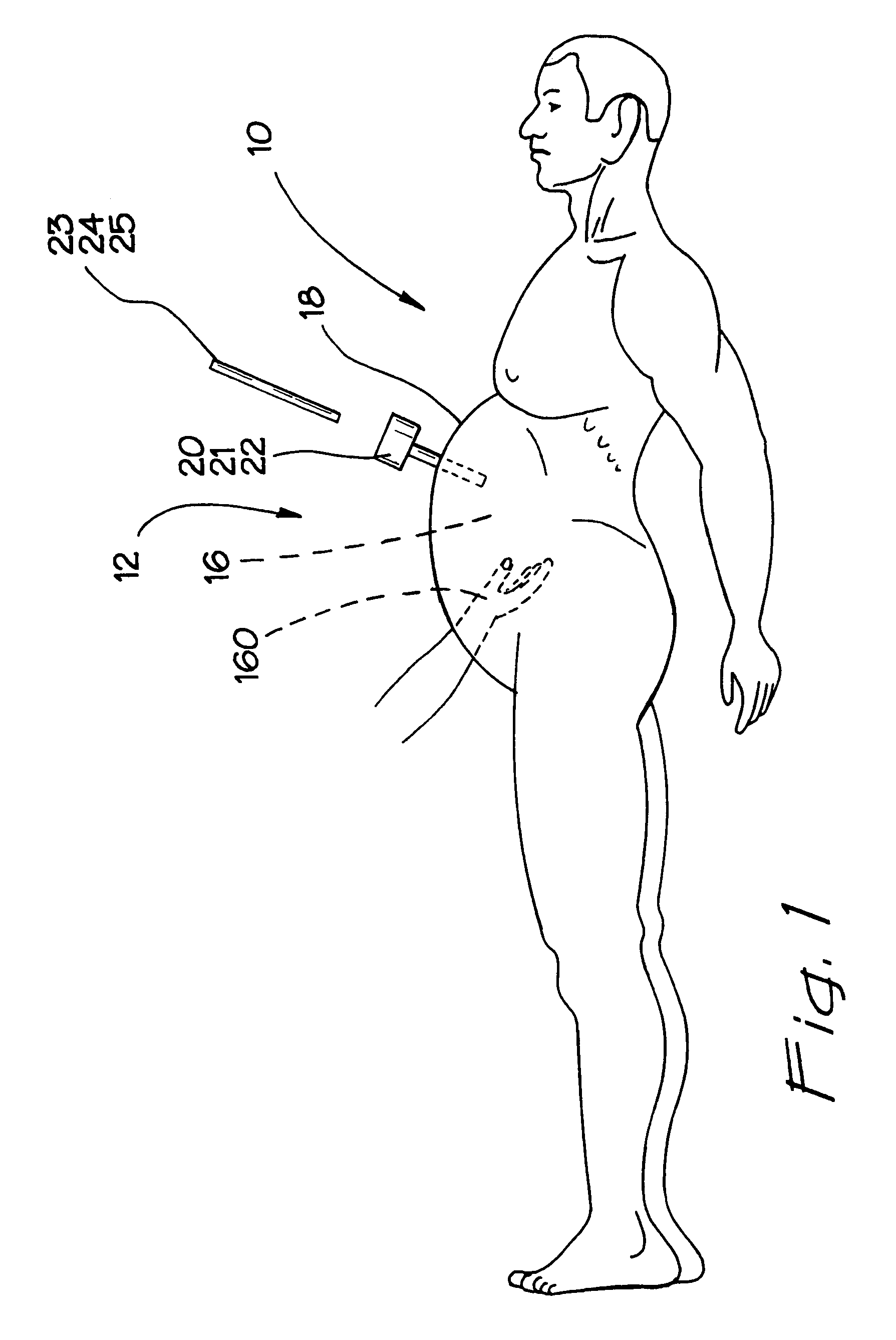
[0061]In FIG. 1, a patient is illustrated in a prone or supine position and designated by the reference numeral 10. The patient 10 has an abdomen 12 which includes a body or abdominal cavity 16 defined by an abdominal wall 18. A plurality of trocars 20, 21, and 22 are placed so as to provide surgical access to the abdominal cavity 16. Various instruments 23, 24, 25 are illustrated for use through the trocars 20, 21, and 22.

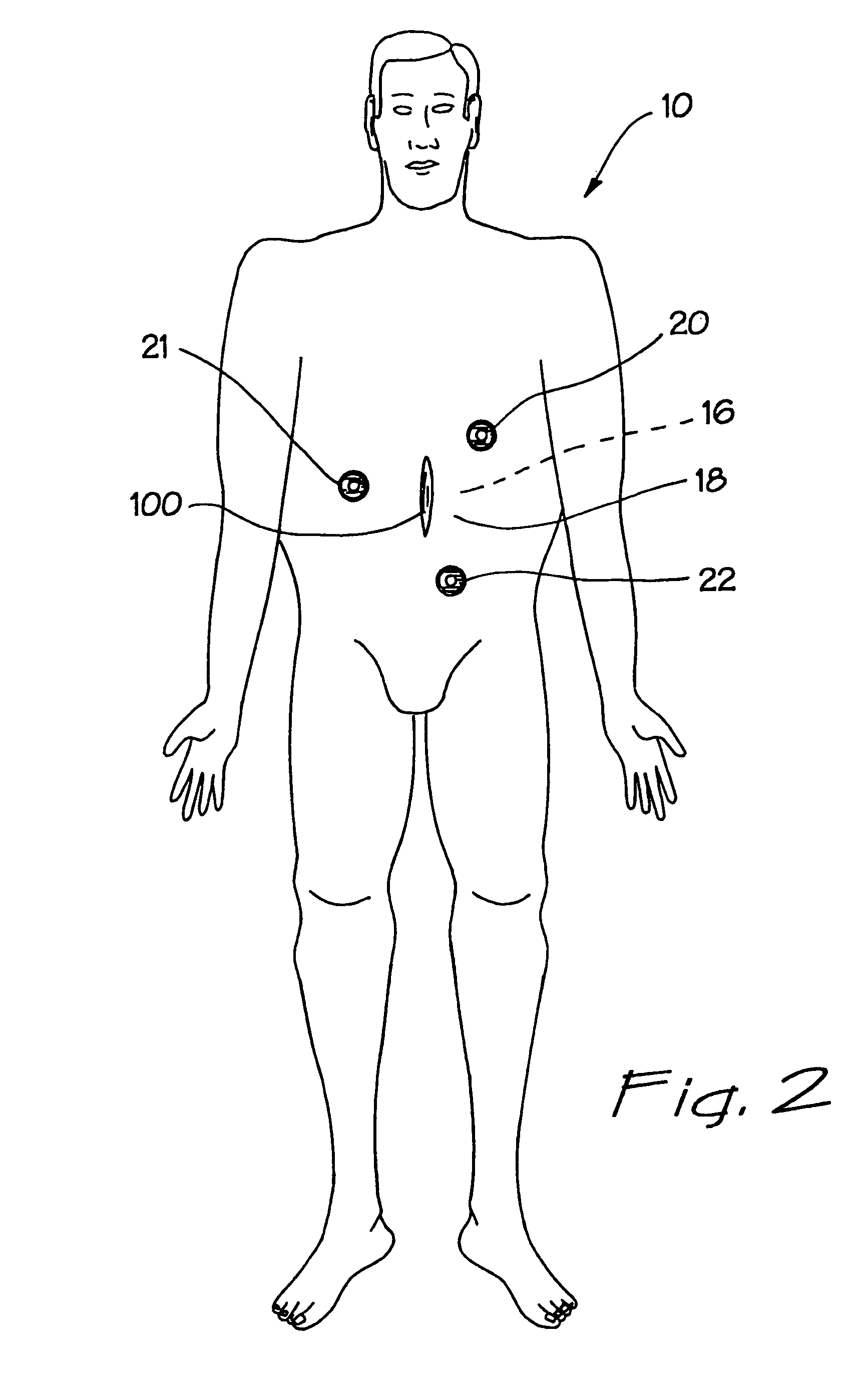
[0062]In FIG. 2, a “hand-assisted” laparoscopic procedure is shown. The patient 10 is supine and the abdominal cavity 16 is insufflated. In addition to the trocars 20, 21, and 22, there is an additional surgical access device 50 that has been placed relative to a surgical incision 100. This access device 50 is adapted to receive a hand 160 of a surgeon, as it is placed through the access device 50 and into the abdominal cavity 16 of the patient 10. The surgeon is able to use the inserted hand 160 to perform tasks that are too difficult or not safe for the instrume...


PUM


Abstract

A surgical access device is adapted to facilitate access through an incision in a body wall having an inner surface and an outer surface, and into a body cavity of a patient. The device includes first and second retention members adapted to be disposed in proximity to the outer surface and the inner surface of the body wall, respectively. A membrane extending between the two retention members forms a throat which is adapted to extend through the incision and form a first funnel extending from the first retention member into the throat, and a second funnel extending from the second retention member into the throat. The throat of the membrane has characteristics for forming an instrument seal in the presence of an instrument and a zero seal in the absence of an instrument. The first retention member may include a ring with either a fixed or variable diameter. The ring can be formed in first and second sections, each having two ends. Couplings can be disposed between the ends to accommodate variations in the size of the first retention member. The first retention member can also be formed as an inflatable toroid, a self-expanding foam, or a circumferential spring. A plurality of inflatable chambers can also provide the surgical access device with a working channel adapted for disposition across the body wall. A first retention member with a plurality of retention stations functions with a plurality of tethers connected to the membrane to change the shape of the membrane and the working channel. A stabilizing platform can be used to support the access device generally independent of any movement of the body wall.

Description

CROSS REFERENCE TO RELATED APPLICATIONS[0001]This is a non-provisional application claiming the priority of PCT application Ser. No. PCT / US02 / 50160, filed on Oct. 20, 2001, and entitled ”Sealed Surgical Access Device, ” which is fully incorporated herein by reference.BACKGROUND OF THE INVENTION[0002]1. Field of Invention[0003]This invention relates generally to surgical access devices, and more specifically to access devices adapted for use in minimal invasive surgery to provide sealed instrument access across a body wall and into a body cavity.[0004]2. Discussion of Related Art[0005]Surgical access to a body cavity, such as the abdominal cavity, is referred to as “open laparotomy” or “closed laparoscopy.” An open procedure involves an incision of sufficient size to allow a surgeon to place hands and instruments within the surgical site. In addition, the site must be open enough for the surgeon to clearly see what he or she is doing. There is often a need for multiple retractors, cl...

Claims


Application Information

Patent Timeline
Patent Type & Authority Patents(United States)
IPC IPC(8): A61B1/04A61B17/00A61B17/02A61B17/34A61B19/00
CPCA61B17/3423A61B17/3462A61B17/0293A61B17/3498A61B19/26A61B2017/3492A61B2017/3405A61B2017/3482A61B2017/3484A61B2017/3486A61B2017/00265A61B90/50
Inventor TAYLOR, SCOTT
Owner APPL MEDICAL RESOURCES CORP
Why Eureka
Try Eureka