System and method for communicating alarm conditions in a mesh network

a wireless device and alarm technology, applied in the field of wireless communication, can solve the problems of inability to inability to detect a condition remotely or exercise control over a system, and inability to monitor and control devices in areas where remote sensors and controllers are positioned miles away from the central control area instead of feet,

Inactive Publication Date: 2006-05-30
NIVIS
View PDF32 Cites 132 Cited by
  • Summary
  • Abstract
  • Description
  • Claims
  • Application Information

AI Technical Summary

Problems solved by technology

The monitoring and controlling of devices located remotely from a central location has historically provided many challenges.
The ability to detect a condition at a remotely located position or to exercise control over a system (such as turning a device off and on) from a central location has oftentimes been limited by the distance of the central control location from the device that is monitored or controlled.
However, hardwired monitoring and controlling of devices in areas wherein the remotely located sensors and controllers are positioned miles away from the central control area instead of feet becomes impractical due to the inability to communicate electrical control signals between the central control room and the remotely located sensor or controller.
However, a problem with this configuration is that data is collected from an individual meter in the geographic area of meters when the utility personnel comes within the broadcast range of the individual meters at each location.
While this is an improvement over utility personnel having to physically inspect and read each individual meter, the problem of this configuration is that it still relies on a human for data collection.
However, difficulties in communicating the data across the same line that carries high voltage electricity has encountered many difficulties, thereby making this approach less practical.
So this solution is limited, at best.
However, the problem with this proposal is that it involves other parties, such as a telephone company, for implementing the system and also suffers from a lack of priority.
For example, when the homeowner is using the telephone line, the modem in the meter cannot acquisition the line.
Requiring utility consumers to procure second telephone lines for meter communication is impracticable and s...

Method used


Image

  • System and method for communicating alarm conditions in a mesh network
  • System and method for communicating alarm conditions in a mesh network
  • System and method for communicating alarm conditions in a mesh network

Examples


Embodiment Construction

[0034]In addition to the drawings discussed above, this description describes one or more embodiments as illustrated in the above-referenced drawings. However, there is no intent to limit this disclosure to a single embodiment or embodiments that are disclosed herein. On the contrary, the intent is to cover all alternatives, modifications, and equivalents included within the spirit and scope of this disclosure and as defined by the appended claims.

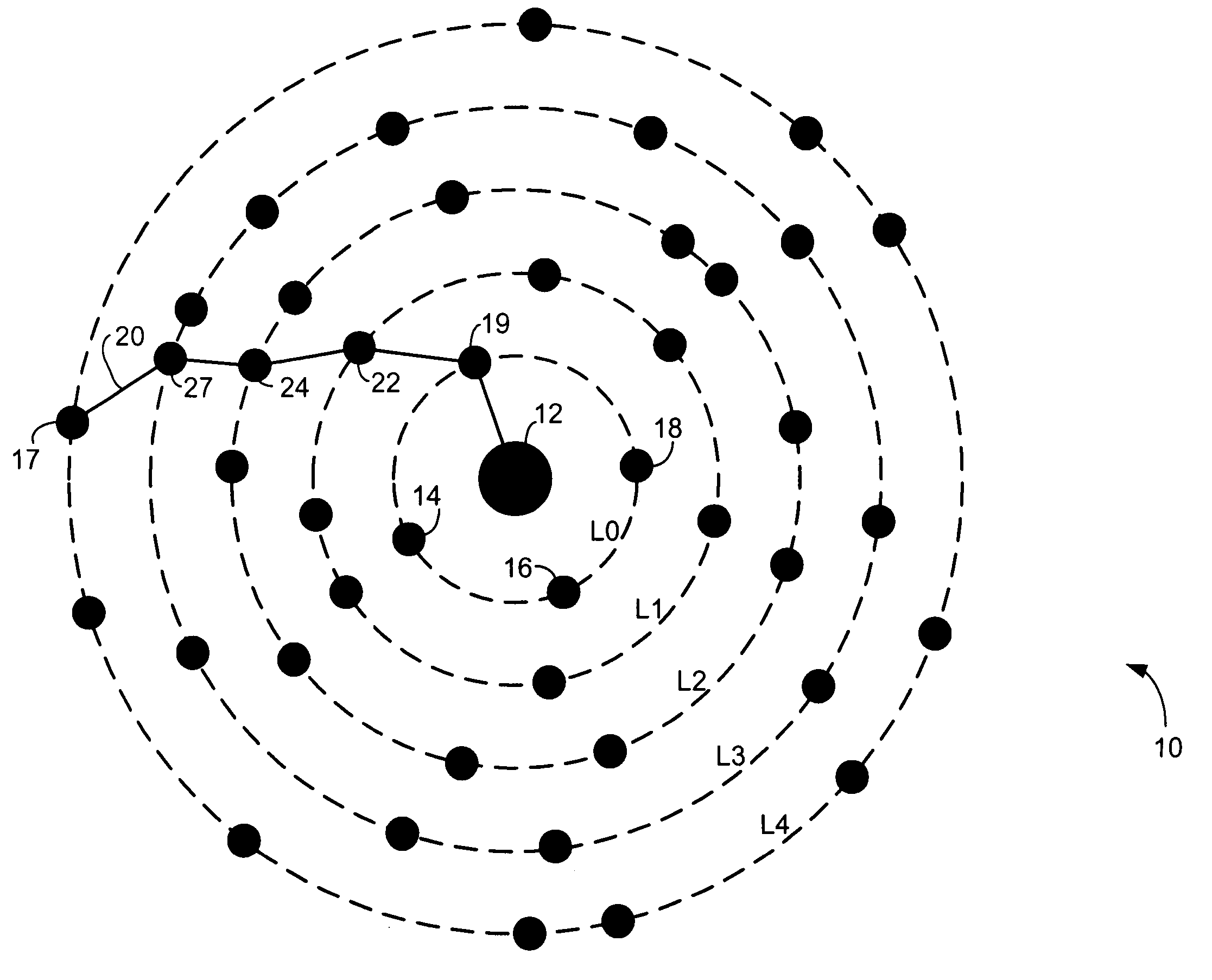
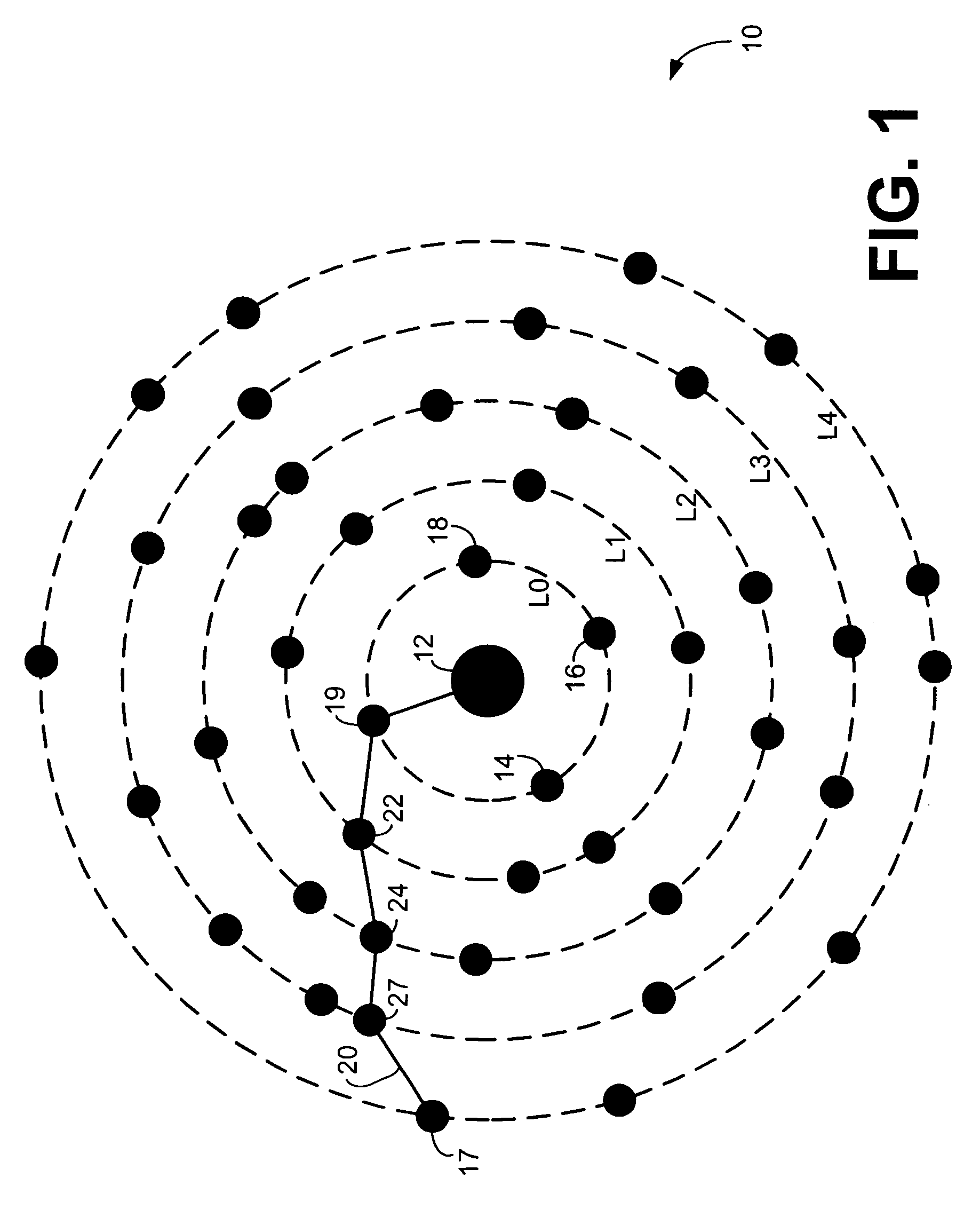
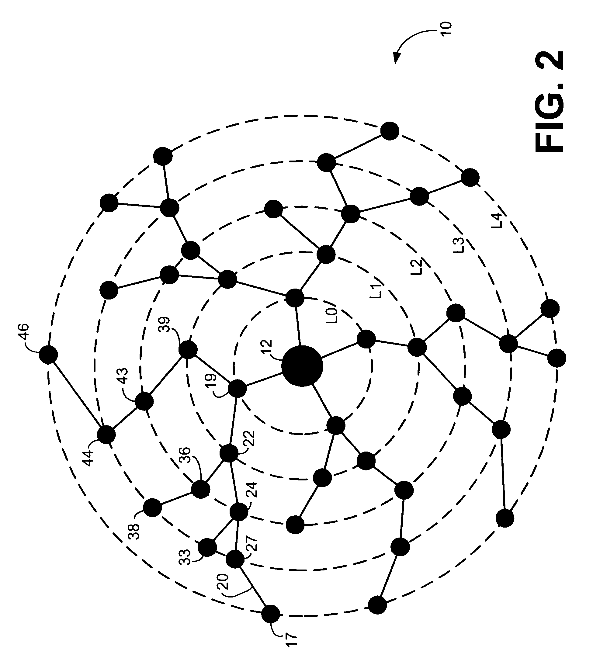
[0035]Each of a plurality of satellite nodes coupled to a meter and logically dispersed around an access node are configured to wirelessly communicate alarm conditions. A first satellite node detects and accesses an alarm condition and then prepares an alarm message containing an alarm code corresponding to the alarm condition and an address indication. The first satellite node may thereafter receive alarm messages from other satellite nodes logically further from the access node than the first satellite node. Alarm codes contained in the ...


PUM


Abstract

Each of a plurality of satellite nodes coupled to a sensing device or an actuator and logically dispersed around an access node are configured to wirelessly communicate alarm conditions. A first satellite node detects and accesses an alarm condition and then prepares an alarm message containing an alarm code corresponding to the alarm condition and an address indication. The first satellite node may thereafter receive alarm messages from other satellite nodes logically further from the access node than the first satellite node. Alarm codes contained in the received alarm messages are filtered and compared to the alarm code of the prepared alarm message. The first satellite node includes a sender address in the prepared alarm message for each received alarm message containing an alarm code that matches the alarm code of the prepared alarm message. The first satellite node transmits the prepared alarm message to the access node.

Description

TECHNICAL FIELD[0001]This disclosure generally pertains to wireless communications and, more particularly, to a system, method, and apparatus for meshing a network of wireless devices.BACKGROUND[0002]The monitoring and controlling of devices located remotely from a central location has historically provided many challenges. The ability to detect a condition at a remotely located position or to exercise control over a system (such as turning a device off and on) from a central location has oftentimes been limited by the distance of the central control location from the device that is monitored or controlled. For example, monitoring and controlling devices within a manufacturing facility or a power plant may be accomplished by hardwiring the sensors and controllers with monitors and controllers in the central control room that may be only a few hundred feet away. However, hardwired monitoring and controlling of devices in areas wherein the remotely located sensors and controllers are ...

Claims


Application Information

Patent Timeline
IPC IPC(8): G08B1/08G08B13/00G08B13/24G08B23/00
CPCG05B23/027H04L67/12G08B25/009
Inventor RATIU, OVIDIUCHILOM, MARIUS OVIDIUTICUS, ION
Owner NIVIS
Why Eureka
Try Eureka