3-D display device
a display device and display technology, applied in the field of 3d observation, can solve the problems of troublesome wearing glasses and the like to achieve the effect of 3-d viewing, inability to achieve wide field angle and large eye relief simultaneously, and inability to achieve wide field angle and large eye reli
- Summary
- Abstract
- Description
- Claims
- Application Information
AI Technical Summary
Benefits of technology
Problems solved by technology
Method used
Image
Examples
embodiment 1
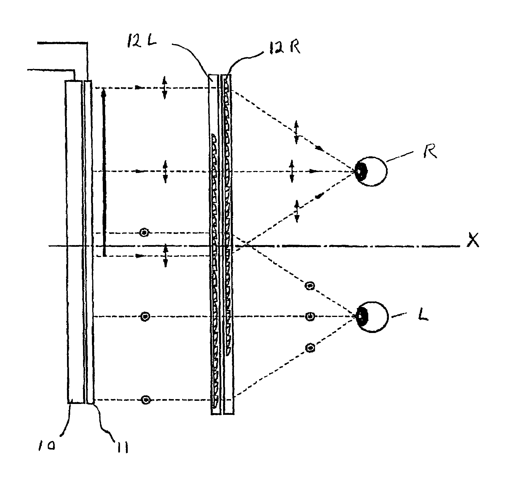
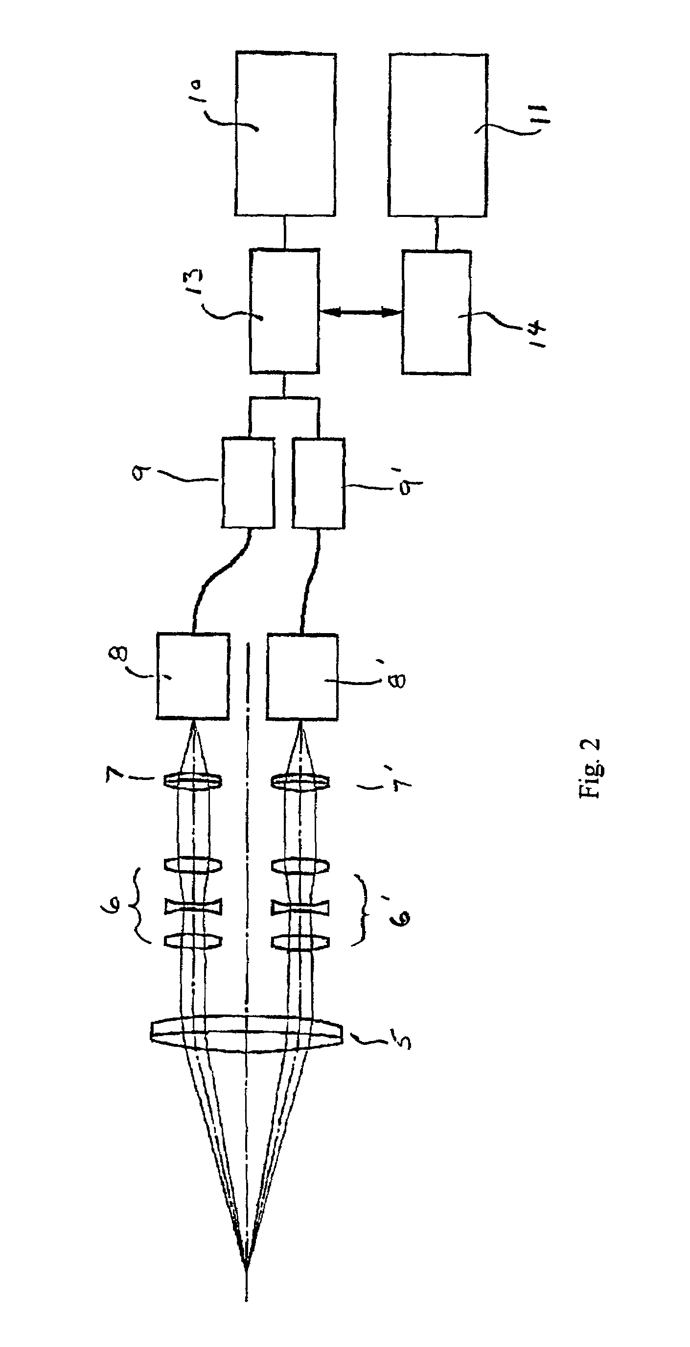
[0040]FIG. 3 shows the configuration of components of the left and right optical path systems of Embodiment 1, and FIG. 4 shows the configuration of the left and right optical path systems 12L, 12R of the display device of this embodiment, as well as a viewer's left and right eyes L, R viewing the display device.
[0041]Referring first to FIG. 4, this display device is formed of a display panel 10, a polarization direction control element 11 (which changes the polarization direction, alternately, in order to sequentially display left and right images), and left and right optical systems for respective left and right optical paths 12L and 12R. The left and right images are thus displayed on the display panel alternately in a time-division manner.
[0042]FIGS. 5A and 5B show the manner in which these images are displayed. As can be seen, the two images are displayed on left and right portions of the display panel, alternately, so that the two images overlap in space, but not in time, in a...
embodiment 2
[0051]FIG. 6 shows the entire configuration of the display device of Embodiment 2. This embodiment has the same characteristics as Embodiment 1 except that there is an interpupillary distance adjustment mechanism as well as a mechanism to change the distance between the left and right displayed images.
[0052]The interpupillary distance adjustment mechanism is formed by an optical viewing system having left and right optical axes, the distance between which is variable and may be adjusted by the viewer. In this embodiment a sensor 18 is provided for measuring the interpupillary distance selected by the user, and the distance between the left and right images on the display panel 10 is automatically adjusted to correspond to the interpupillary distance. Camera control parts 9, 9′ receive a signal for changing the display timing to change the display distance between the left and right images on the display panel 10 according to a signal from the sensor 18. For adjusting the interpupill...
embodiment 3
[0054]FIG. 7 shows Embodiment 3 in which plural sets of optical systems having independent optical axes are arranged in the light path between a display and a viewer. Embodiment 3 has the same basic configuration as Embodiment 1, with only the differences being described hereinafter.
[0055]In this embodiment more than one optical system is placed in each of the left and right optical axis. For example, when the eye relief is 50 mm, the field angle is 60 degrees, and the interpupillary distance is 55 mm, the left and right light fluxes are overlapped 5 mm. For ensuring a 50 mm eye relief, the focal length of the optical system has to be approximately 50 mm. Thus, in order to ensure sufficient power of the optical system for the purpose of downsizing by using a shorter focal length, more than one optical system is placed on the left and right optical axes in order to shorten the focal length. Thus, a first right optical path system 12R and a second right optical path system 12R′ are pl...
PUM
 Abstract
Description
Claims
Application Information
 - R&D
- Intellectual Property
- Life Sciences
- Materials
- Tech Scout
- Unparalleled Data Quality
- Higher Quality Content
- 60% Fewer Hallucinations
Browse by: Latest US Patents, China's latest patents, Technical Efficacy Thesaurus, Application Domain, Technology Topic, Popular Technical Reports.
© 2025 PatSnap. All rights reserved.Legal|Privacy policy|Modern Slavery Act Transparency Statement|Sitemap|About US| Contact US: help@patsnap.com


