Visualizing Birefringent Structures in Samples

a birefringent structure and sample technology, applied in the field of polarized light to visualize structures, can solve the problems of difficult detection of retardance below 5 nm, limited sensitivity of these methods, and unpredictable details of patterns seen, blinking and blinking.

Active Publication Date: 2009-05-28
CAMBRIDGE RES & INSTR
View PDF3 Cites 10 Cited by
  • Summary
  • Abstract
  • Description
  • Claims
  • Application Information

AI Technical Summary

Benefits of technology

[0050]In one embodiment of this type, the system transmits light over a wide spectra...

Problems solved by technology

The sensitivity of these methods is limited, and it is difficult to detect retardance is below 5 nm.
The details of what patterns are seen, and how they change during blinking, are unpredictable.
This is an unsatisfactory arrangement for several reasons: it is visually tiring due to the stroboscopic blink action; some people never attain competence at resolving structures against the background, or attain only limited competence so can only see the most highly birefringent structures; and the variable and uncontrolled nature of the spatial patterns make it hard to predict whether good results will be obtained in any given setup.
However, each of these has strengths and weaknesses, and in general no one technique is effective in all cases.
All are of limited value for observing spindle structures in oocytes.
This art involves complicated and costly systems with a digitized camera and a personal computer; first to perform the initial calibration and setup; and ...

Method used


Image

  • Visualizing Birefringent Structures in Samples
  • Visualizing Birefringent Structures in Samples
  • Visualizing Birefringent Structures in Samples

Examples


Embodiment Construction

[0060]The invention concerns use of two elliptical polarizers, one of which exhibits a time-varying ellipticity, to visualize birefringent structures in samples. This produces a time-modulated visual scene, in which birefringent structures are evident because their appearance is different from the background.

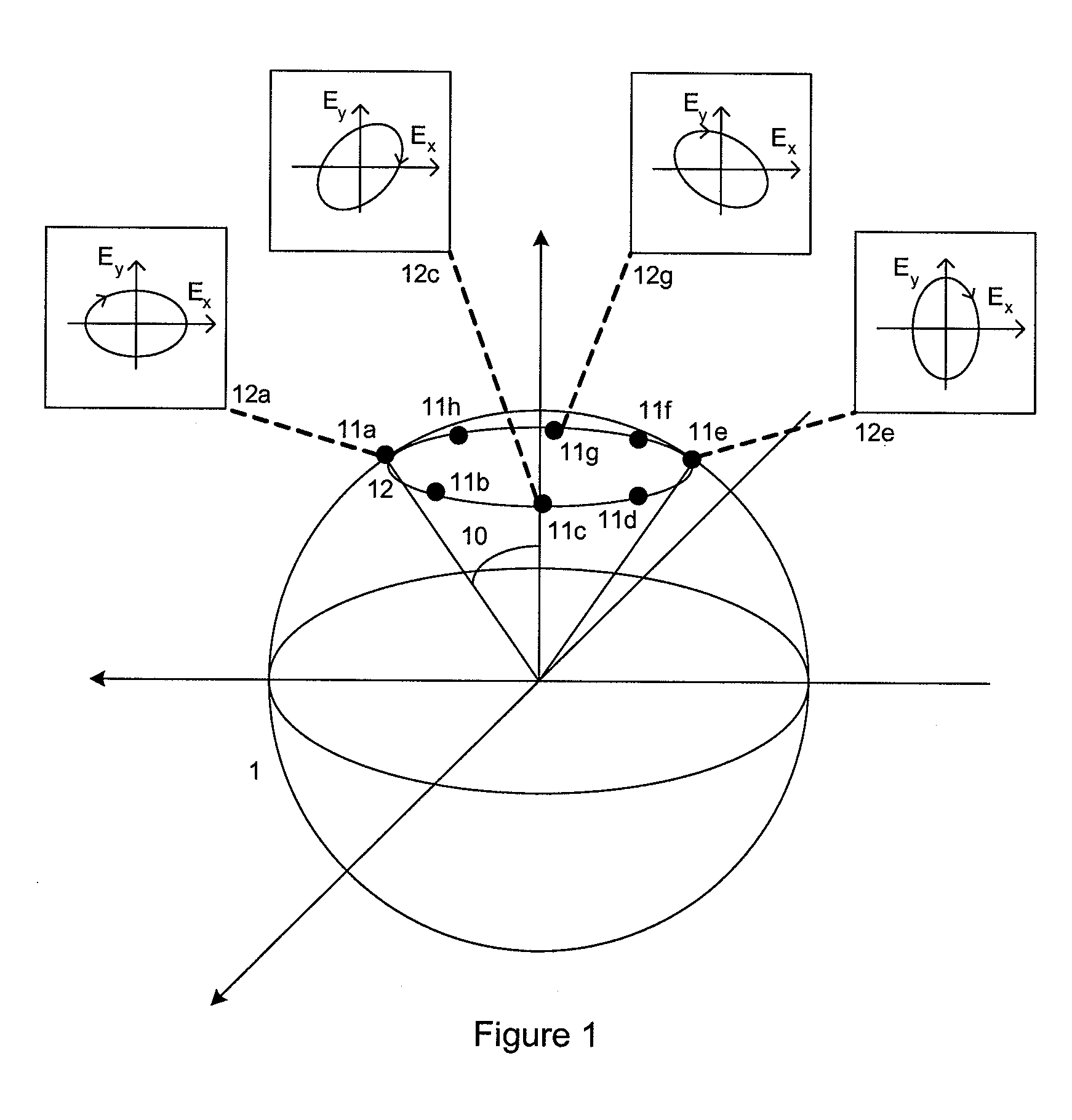
[0061]One aspect of the invention is to provide modulation between four or more states that lie substantially on the same latitude on the Poincare sphere, as illustrated in FIG. 1. In this embodiment, either the entrance polarizer or analyzer polarizer is substantially a circular polarizer corresponding to the South pole on the Poincare sphere, and the other polarizer expresses the points 11a, 11c, 11e, and 11g. The poles may be reversed, so that the circular polarizer is substantially located at the North pole of the Poincare sphere while the other polarizer executes a series of states surrounding the South pole. What is important is that one polarizer be substantially a circul...


PUM


Abstract

Apparatus and methods are disclosed for viewing low-birefringence structures within samples directly, with the eye, in real-time. The sample is placed between an entrance polarizer and analyzer polarizer, the transmission state of one of which is changed dynamically to create a modulated view of the scene; against this background, birefringent structures are visible because of their different appearance when modulated. Modulation rates of 4 or more states per second; use of 4 or more states, or even a continuum of states, which lie substantially on a latitude line on the Poincare sphere; and orientation of the polarization components to produce a uniform background; produce a clear view that does not produce operator fatigue. Broad-band wavelength operation spanning 50 nm or more, or the whole visible range, is achieved, and it is compatible with integration into other microscopy modes such as Hoffman relief contrast.

Description

RELATED APPLICATIONS[0001]This application claims priority from U.S. Provisional Patent Application Ser. No. 61 / 003,692, which was filed on Nov. 19, 2007. The entire contents of application 61 / 003,692 are incorporated herein by reference.BACKGROUND OF THE INVENTION[0002]1. Field of the Invention[0003]The present invention is related to the use of polarized light to visualize structures that possess molecular order or that are under strain.[0004]2. Description of the Related Art[0005]Materials having a different optical index of refraction for different states of polarization are said to express birefringence, and the amount of birefringence in a sample is termed its optical retardance. The index of refraction is highest for rays of light having an E field along a first direction, which is termed the fast axis for that sample. It is conventional to describe that direction as the azimuth angle, relative to some coordinate system of interest.[0006]Polarized light has been used to obtai...

Claims


Application Information

Patent Timeline
IPC IPC(8): G01J4/00
CPCG01N21/23G01J4/04
Inventor MILLER, PETERFLETCHER-HOLMES, DAVIDBOUTIN, CATHY M.HOYT, CLIFFORD
Owner CAMBRIDGE RES & INSTR
Why Eureka
Try Eureka