Reduction of average-to-minimum power ratio in communications signals

a technology of communication signals and power ratios, applied in the field of reducing the average-to-minimum power ratio in communications signals, can solve the problems of unpractical modulation formats, and often difficult or essentially impossible to change the modulation, and achieve the effect of reducing the ratio of average power

Inactive Publication Date: 2006-05-30
APPLE INC
View PDF30 Cites 65 Cited by
  • Summary
  • Abstract
  • Description
  • Claims
  • Application Information

AI Technical Summary

Problems solved by technology

Once a modulation technique has been selected for some specific application, it is oftentimes difficult or essentially impossible to change the modulation.
Clearly this is not practical.
In particular, modulation formats that lead to very small magnitude values (relative to the average magnitude value) generally have very large phase component bandwidth.
In this case the bandwidth of the phase component is essentially infinite, and the signal is not amenable to transmission by a polar modulator.
Many commonly employed modulation techniques do in fact lead to very small relative signal magnitude.
By contrast, relatively little work appears to have been done that deals with hole-blowing (which seeks to locally increase signal power), and prior approaches have been found to result in less-than-desired performance.
The motivation given for creating these holes is that certain power amplifiers, in particular LINC power amplifiers, are difficult to implement when the signal amplitude dynamic range is large.
Because the method used by both of these patents to calculate the corrective magnitude and phase is only a very rough approximation, performance is less than desired.
The method does not allow for placement of pulses at arbitrary timing.
As a result, effectiveness is decreased, and EVM (error vector magnitude) suffers.
1) The signal envelope is only tested for a minimum value at half-symbol timing (t=i*T+T / 2).
2) The phase of the correction is not based on the signal envelope, but rather only on the two symbols adjoining the low-magnitude event.
These two restrictions can lead to errors in the magnitude and phase of the corrective pulses.
Specifically, the true signal minimum may occur not at T / 2, but at some slightly different time, so that error will be introduced into the magnitude of the corrective pulses.
For example, this may be a reasonable assumption for a Universal Mobile Telecommunication System (UMTS) uplink signal with one Dedicated Physical Data Channel (DPDCH), but is not a reasonable assumption for a UMTS uplink signal with two DPDCH active.
The size of this magnitude error can be quite large.
In such cases the calculated correction magnitude is much smaller than would be desired, which in turn results in the low-magnitude event not being removed.
However, this approximation is only valid if the origin does not lie between the previously described straight line and the true signal envelope.
This typically leaves a low-magnitude event that is not corrected.
Therefore the same sources of magnitude error and phase error previously noted apply equally to this method.
Large PAR is a problem for many, if not most, conventional power amplifiers (PA).
A signal with a large PAR requires highly linear amplification, which in turn affects the power efficiency of the PA.

Method used


Image

  • Reduction of average-to-minimum power ratio in communications signals
  • Reduction of average-to-minimum power ratio in communications signals
  • Reduction of average-to-minimum power ratio in communications signals

Examples


Embodiment Construction

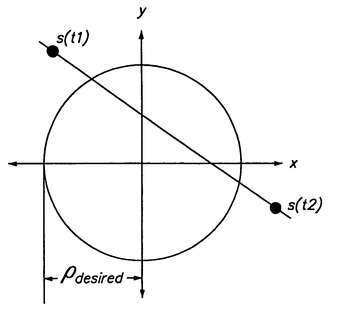
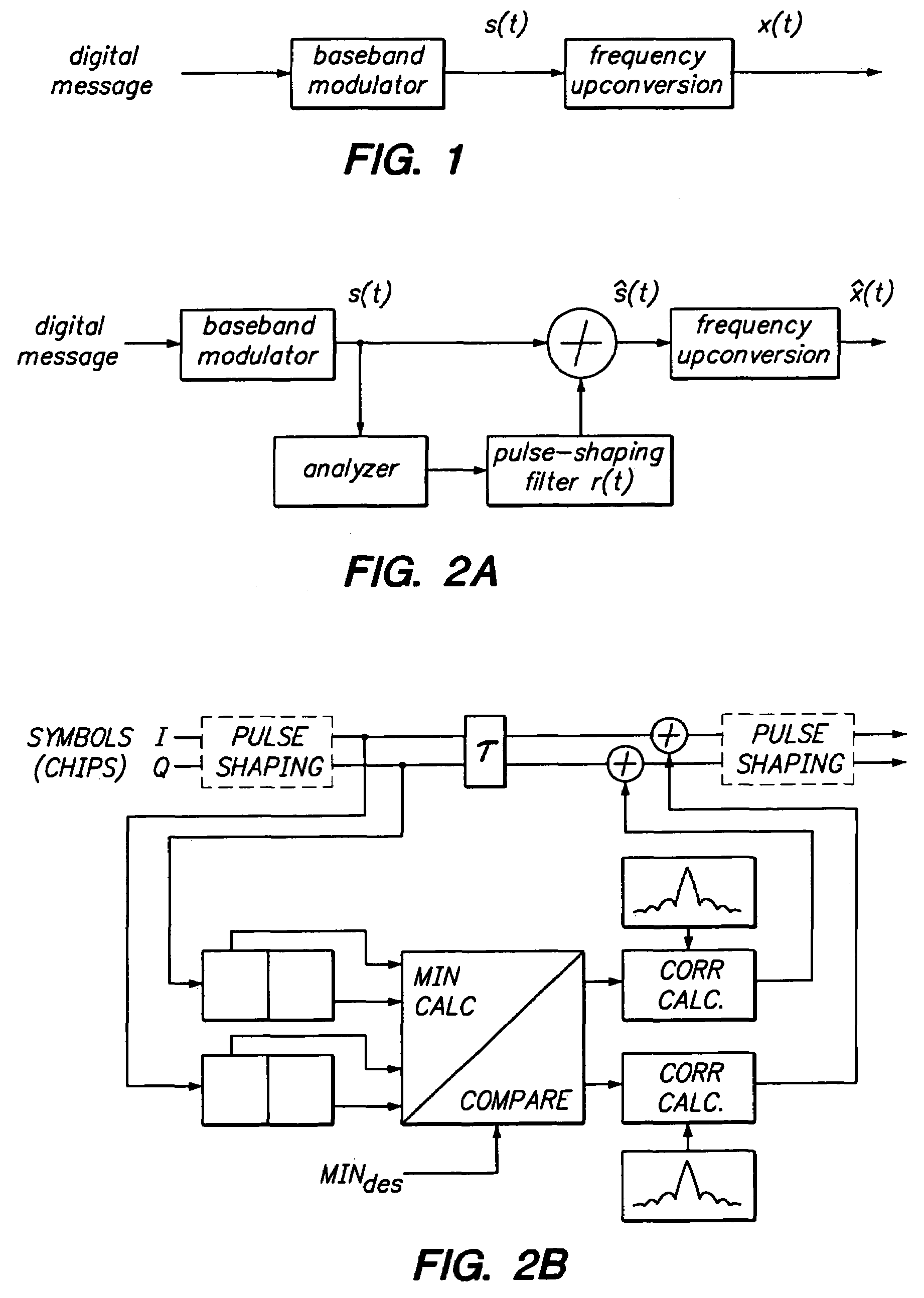
[0076]A polar modulator can be viewed as a combination of a phase modulator and an amplitude modulator. The demands placed on the phase modulator and amplitude modulator are directly dependent on the bandwidth of the signal's phase and magnitude components, respectively. The magnitude and phase bandwidth, in turn, are dependent on the average-to-minimum magnitude ratio (AMR) of the signal. As will be shown later, a signal with large AMR can have very abrupt changes in phase, which means that the signal phase component has significant high frequency content. Furthermore, certain transistor technologies limit the AMR that can be achieved in a practical amplitude modulator. This limitation can lead to distortion of the transmitted signal if the required magnitude dynamic range exceeds that which can be generated by the transistor circuit. Thus minimization of signal AMR is highly desirable if the signal is to be transmitted with a polar modulator. One example of a polar modulator is de...


PUM


Abstract

This invention, generally speaking, modifies pulse amplitude modulated signals to reduce the ratio of average power to minimum power. The signal is modified in such a manner that the signal quality remains acceptable. The signal quality is described in terms of the Power Spectral Density (PSD) and the Error Vector Magnitude (EVM).

Description

FIELD OF THE INVENTION[0001]The present invention relates to the reduction of average-to-minimum power ratio in communications signals.STATE OF THE ART[0002]Many modern digital radio communication systems transmit information by varying both the magnitude and phase of an electromagnetic wave. The process of translating information into the magnitude and phase of the transmitted signal is typically referred to as modulation. Many different modulation techniques are used in communication systems. The choice of modulation technique is typically influenced by the computational complexity needed to generate the signal, the characteristics of the radio channel, and, in mobile radio applications, the need for spectral efficiency, power efficiency and a small form factor. Once a modulation technique has been selected for some specific application, it is oftentimes difficult or essentially impossible to change the modulation. For example, in a cellular radio application all users would be re...

Claims


Application Information

Patent Timeline
Patent Type & Authority Patents(United States)
IPC IPC(8): H03C1/52H04L25/03H04L27/36
CPCH04L25/03866H04L25/03
Inventor BOOTH, RICHARD W. D.SCHELL, STEPHAN V.BIEDKA, THOMAS E.LIANG, PAUL CHENG-PO
Owner APPLE INC
Why Eureka
Try Eureka