Transfer apparatus, image forming apparatus, and method of correcting moving speed of belt

a technology of image forming apparatus and transfer apparatus, which is applied in the direction of electrographic process apparatus, instruments, optics, etc., can solve the problems of increasing the cost, the image forming apparatus is prone to be upsized, and the difficulty of increasing the speed of image formation

Active Publication Date: 2006-05-30
RICOH KK
View PDF6 Cites 24 Cited by
  • Summary
  • Abstract
  • Description
  • Claims
  • Application Information

AI Technical Summary

Benefits of technology

[0026]It is an object of the present invention to solv

Problems solved by technology

However, the one photosensitive element is made to rotate a plurality of times (four times for a full color image) to form a full color image on a sheet, which makes it difficult to increase the speed of image formation.
In the tandem type of image forming apparatus, the image forming apparatus requires a plurality of photosensitive elements, and therefore, the image forming apparatus tends to be upsized, and the cost is increased accordingly.
When these two transfer systems are compared, it is obvious that the former has a disadvantage such that the whole configuration of the image forming apparatus is elongated in a direction of the sheet conveyance

Method used


Image

  • Transfer apparatus, image forming apparatus, and method of correcting moving speed of belt
  • Transfer apparatus, image forming apparatus, and method of correcting moving speed of belt
  • Transfer apparatus, image forming apparatus, and method of correcting moving speed of belt

Examples


first embodiment

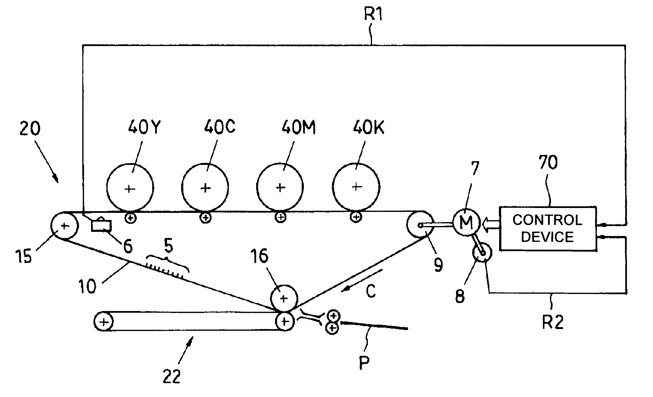
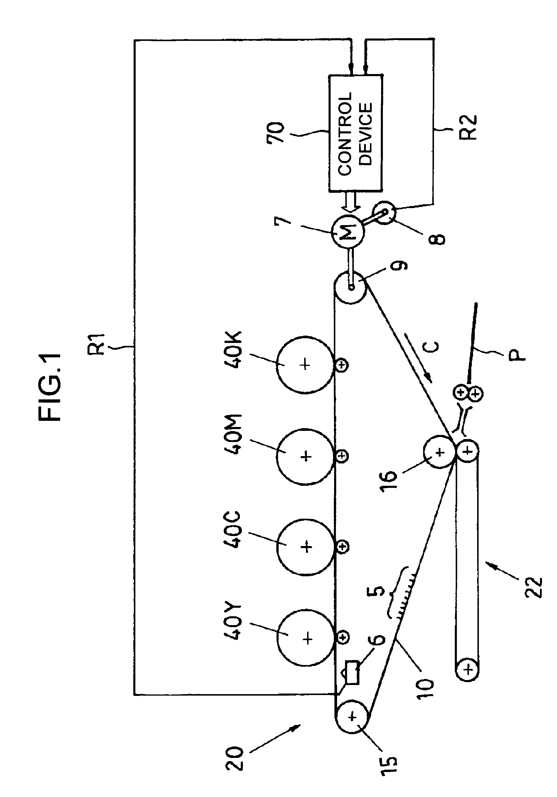
[0060]FIG. 1 is a diagram of a transfer apparatus, together with a control system and a plurality of photosensitive elements, according to the present invention. FIG. 2 is a diagram of an example of an image forming apparatus including the transfer apparatus.

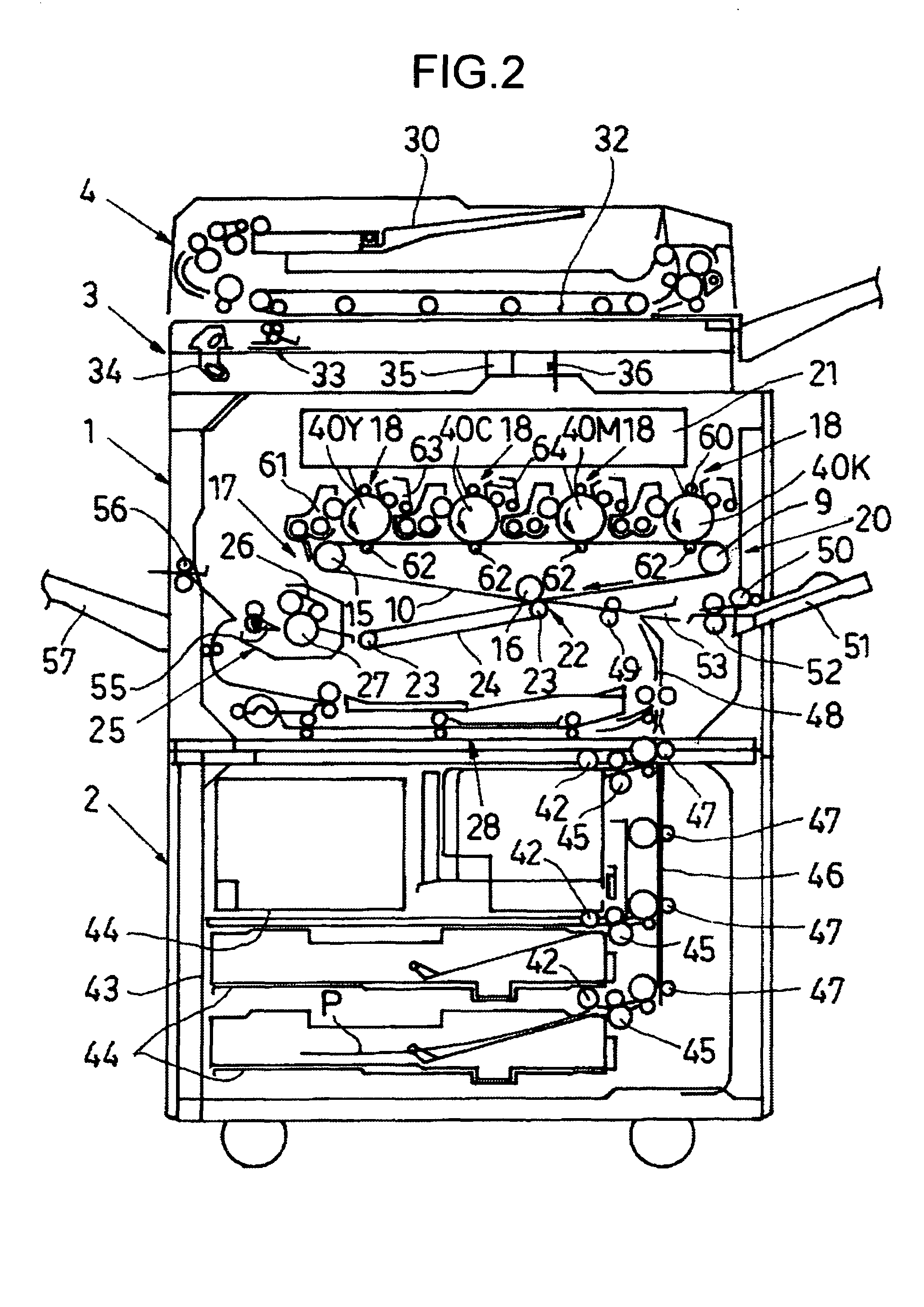
[0061]The image forming apparatus shown in FIG. 2 is a tandem type electrophotographic device using an endless intermediate transfer belt 10 (hereinafter, “transfer belt 10”). The image forming apparatus will be assumed to be a copying machine. A body 1 of the copying machine is placed on a paper feed table 2. A scanner 3 is mounted on the body 1, and an automatic document feeder (ADF) 4 is mounted on the scanner 3.

[0062]A transfer apparatus 20 that includes the transfer belt 10 is provided at substantially the central part of the body 1. The transfer belt 10 is supported by a drive roller 9 and two driven rollers 15 and 16 so as to move clockwise (see FIG. 2). Toner remaining on the surface of the transfer belt 10 after an imag...

second embodiment

[0117]FIG. 9 is a diagram of a transfer apparatus of an image forming apparatus that detects a speed of the transfer belt 10 from the number of revolutions of a driven roller 15 for supporting the transfer belt 10, together with a control system as shown in FIG. 1, according to the present invention. FIG. 10 is a block diagram of two control loops included in the image forming apparatus.

[0118]The image forming apparatus according to the second embodiment is different, from the image forming apparatus of FIG. 2, only in that the moving speed of the transfer belt 10 is detected from the rotating speed of the driven roller 15 that supports the transfer belt 10. Therefore, the illustration of the overall configuration of the image forming apparatus and explanation thereof are omitted, and only the difference is explained below.

[0119]The transfer apparatus of the image forming apparatus includes another control loop used on occurrence of abnormality (hereinafter, “tertiary control loop”)...

third embodiment

[0125]FIG. 11 is a flowchart with respect to the operation of an image forming apparatus including a transfer apparatus that controls a belt speed according to a difference between an actual speed and a target speed of the belt detected respectively by the primary control loop and the secondary control loop, according to the present invention.

[0126]The components and the control system of the transfer apparatus and the image forming apparatus of the third embodiment are the same as those explained with reference to FIG. 1 and FIG. 2. Therefore, the illustration and the explanation thereof are omitted (but FIG. 1 and FIG. 2 are referred to as required). Only the processing implemented by the microcomputer of a control device (which is configured the same as that of the control device 70) is explained. The processing is implemented following the method of correcting the moving speed of the belt 10.

[0127]In the microcomputer of the control device 70, if both the primary control loop R1...


PUM


Abstract

A scale is provided along at least one side of a portion of a belt. A sensor reads the scale on the belt to obtain scale information. An actual speed calculating unit calculates a speed of the belt from the scale information. A speed calculating unit calculates a speed of the belt from information other than the scale information. A control unit that provides a control to correct speed of the belt according to the speed calculated by the actual speed calculating unit when the speed calculated by the actual speed calculating unit is normal, and provides a control to correct speed of the belt according to the speed calculated by the speed calculating unit when the speed calculated by the actual speed calculating unit is abnormal.

Description

CROSS-REFERENCE TO RELATED APPLICATIONS[0001]The present document incorporates by reference the entire contents of Japanese priority document, 2002-378033 filed in Japan on Dec. 26, 2002, and 2003-423764 filed in Japan on Dec. 19, 2003.BACKGROUND OF THE INVENTION[0002]1) Field of the Invention[0003]The present invention relates to a transfer apparatus that reads a scale, provided along the whole circumference of a belt that is made to rotate, by a sensor, and detects an actual speed of the belt based on information from the scale to correct a speed of the belt to a target speed according to the detected actual speed, and an image forming apparatus and a method of correcting the moving speed of the belt.[0004]2) Description of the Related Art[0005]Copying machines and printers as an image forming apparatus using an electrophotographic system have, in many cases, a function of forming a full color image according to increasing demands of the market.[0006]The image forming apparatus ca...

Claims


Application Information

Patent Timeline
IPC IPC(8): G03G15/16G03G21/14G03G15/01
CPCG03G15/161G03G2215/1623
Inventor KURODA, HIROYUKI
Owner RICOH KK
Why Eureka
Try Eureka