Electronic control for glass moulding machines

a technology of electronic control and glass moulding machine, which is applied in the direction of glass blowing apparatus, glass shaping apparatus, instruments, etc., can solve the problems of high cost and effectiveness, high construction and wiring costs, and high cost of control system architecture, and achieve the effect of rapid input of messages and rapid access to these messages

Inactive Publication Date: 2006-05-30
HEYE INT
View PDF11 Cites 22 Cited by
  • Summary
  • Abstract
  • Description
  • Claims
  • Application Information

AI Technical Summary

Benefits of technology

[0008]This object is achieved by the present invention which provides a control for at least one glass forming machine. Here, each of the glass forming machines has an electronic control and a plurality of mechanisms and includes a first drive having a programmable movement profile and which drives one of the mechanisms; another first drive having a programable movement profile and which drives a second one of the mechanisms, the second mechanism opening and closing at pre-programable positions a first valve; a second drive with a non-programmable movement profile which can be activated and shut down by a second valve at programmable times, wherein the second drive drives a third one of the mechanisms; and a third valve which can be opened and closed at programmable times. A plurality of first controllers is provided, each of such first controllers are connected to at least one of the first drives, the second valve or the third valve. Also included is control means for controlling all of the first controllers, the control means having a first sequencer formed as a microprocessor, and all of the first controllers are connected to the first sequencer via a first bus. Practically all functions of the at least one glass forming machine are thereby controllable in a networked manner. By means of the bus system the known master-slave-system is consciously discarded and a message-orientated system is created. In this way very rapid input of messages and also rapid access to these messages from anywhere are made possible.

Problems solved by technology

The cost is high and effectiveness is limited.
The constructional and wiring expense is also considerable in this case.
This control system architecture is expensive.
Faults in, or the failure of the central control unit lead to the whole production installation being disrupted or shut down.
This architecture is even more expensive.
Faults in, or failure of a central unit lead to the whole I.S. glass forming machine being disrupted.

Method used


Image

  • Electronic control for glass moulding machines
  • Electronic control for glass moulding machines
  • Electronic control for glass moulding machines

Examples


Embodiment Construction

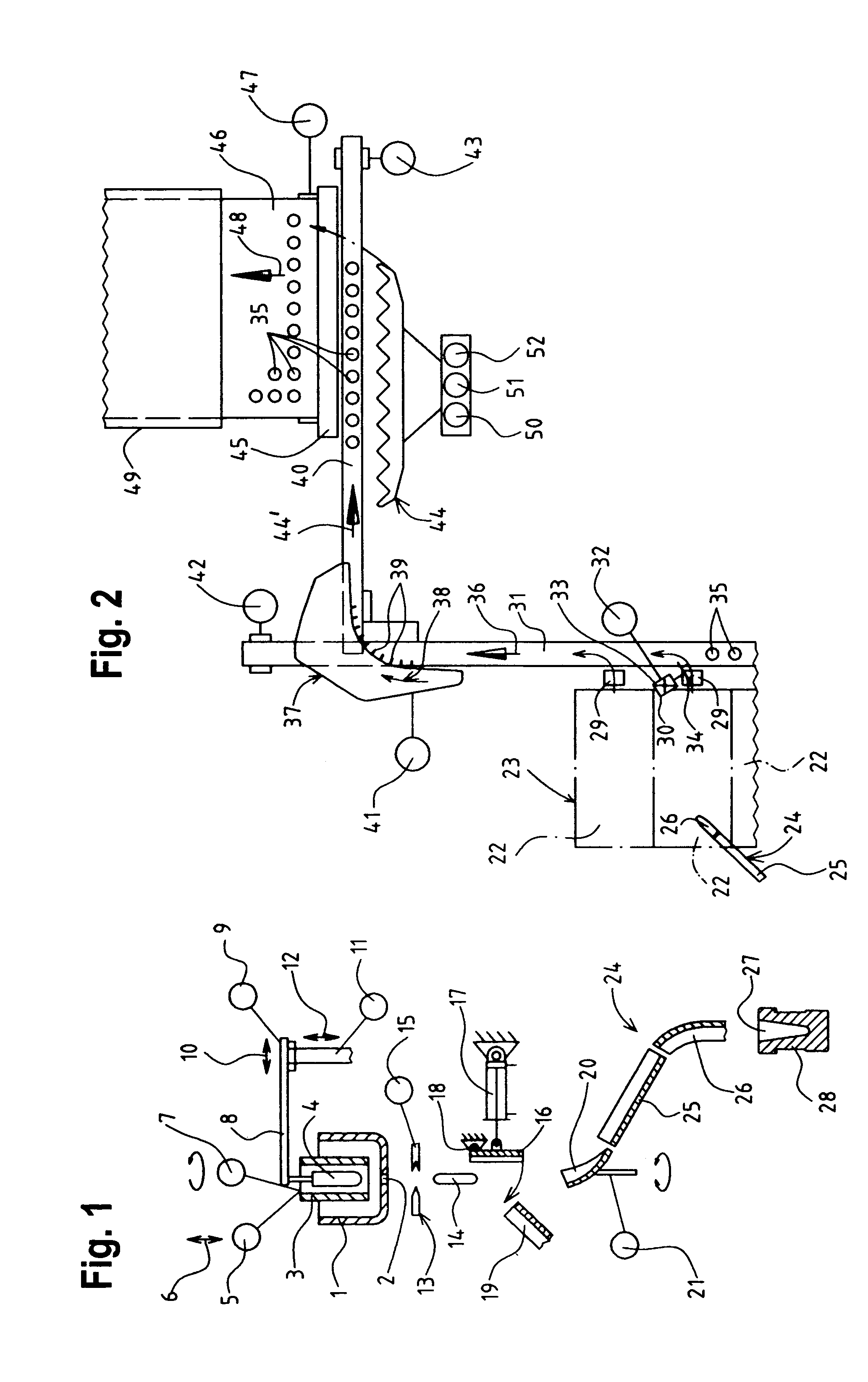
[0015]In FIG. 1 a feeder head 1 contains molten glass which exits as a glass extrusion through an outlet orifice 2. The manner in which it exits is influenced in a manner which is known per se by a rotating cylinder 3 and / or a plunger 4. The rotating cylinder 3 can be raised and lowered in the directions of a double arrow 6 by means of a third drive 5, indicated only schematically, and can be rotated around a vertical axis by means of a further third drive 7.

[0016]The plunger 4 is disposed inside the rotating cylinder 3 and held by a carrier device 8. The carrier device 8 can be adjusted in the horizontal direction in the directions of the double arrow 10 by a third drive 9 and can be raised and lowered in the directions of a double arrow 12 by a further third drive 11.

[0017]Gobs 14 of molten glass are periodically separated, by means of gob shears 13, from the glass extrusion leaving the outlet orifice 2. The gob shears 13 are driven by a third drive 15. Normally the gobs 14 fall f...


PUM

PropertyMeasurementUnit
massaaaaaaaaaa
electricalaaaaaaaaaa
flexibleaaaaaaaaaa

Abstract

Sections (22) of an I.S. glass forming machine (23) have a plurality of mechanisms which can be respectively driven by a first drive. Each first drive is allocated a controller which is connected to a first sequencer (60) via a first bus (59). All first sequencers (60) are connected to a second bus (70) to which a second sequencer (71), a manually-operated device (72), a PC (73) with an Internet connection (74) and a modem (75) are connected. Peripheral devices of the I.S. glass forming machine (23) each have at least one third drive (5, 7, 9, 11, 15, 21, 32, 41, 42, 43, 50, 51, 52, 17, 82). Each third drive is connected to a first control device (77). In the case of the third drives (17, 82) associated first control devices (77) are directly connected to the second bus (70), whereas in the other cases a plurality of first control devices (77) are connected to a third bus (78) which is connected to the second bus (70) via a second control device (79).

Description

BACKGROUND[0001]The invention relates to an electronic control for a glass forming machine.[0002]In the case of a known control of this type (EP 0 603 011 B1) all controllers of the glass forming machine are connected to a common synchronization signal line and are also connected to each other by a stop line which is directed to one side, by a LAN (Local Area Network), by a bi-directional maintenance stop line and by a parallel-distribution transition signal line. One of the controllers has the additional task of controlling all other controllers. The cost is high and effectiveness is limited.[0003]From U.S. Pat. No. 4,685,947 A it is known per se to control the controllers of the mechanisms of each section of the glass forming machine by means of a section controller. All section controllers are monitored by a common monitoring controller. An additional machine controller is connected to all controllers and to the monitoring controller. The constructional and wiring expense is also...

Claims


Application Information

Patent Timeline
Patent Type & Authority Patents(United States)
IPC IPC(8): G06F19/00C03B9/41
CPCC03B9/41
Inventor HARTMANN, THOMASWINKELHAKE, DIRK
Owner HEYE INT
Why Eureka
Try Eureka