System, method, and program for robot control

a robot control and program technology, applied in the field of system control, can solve the problems of increasing the manufacturing cost of the control software, affecting the operation of the robot control system, and the hardware range of the robot that uses a combination of arms and tails, and cannot be handled

Inactive Publication Date: 2006-05-30
NEC CORP
View PDF13 Cites 9 Cited by
  • Summary
  • Abstract
  • Description
  • Claims
  • Application Information

AI Technical Summary

Problems solved by technology

In an approach described in the above-mentioned publication (JP Patent Kokai JP-P2000-267852A), variations of software components required for altering the configuration need to be included in the control software in advance, so that a problem arises that the manufacturing cost of the control software increases.
Further, the hardware range of the robot that can be handled is also limited.
If control software that includes software components of the arms, feet, and head is made so as to accommodate any one of the combinations of the arms and the feet, arms and the head, and the feet and the arms, for example, the hardware of the robot that uses a combination of the arms and a tail, which is not predicted by the control software, cannot be handled.

Method used


Image

  • System, method, and program for robot control
  • System, method, and program for robot control
  • System, method, and program for robot control

Examples


first embodiment

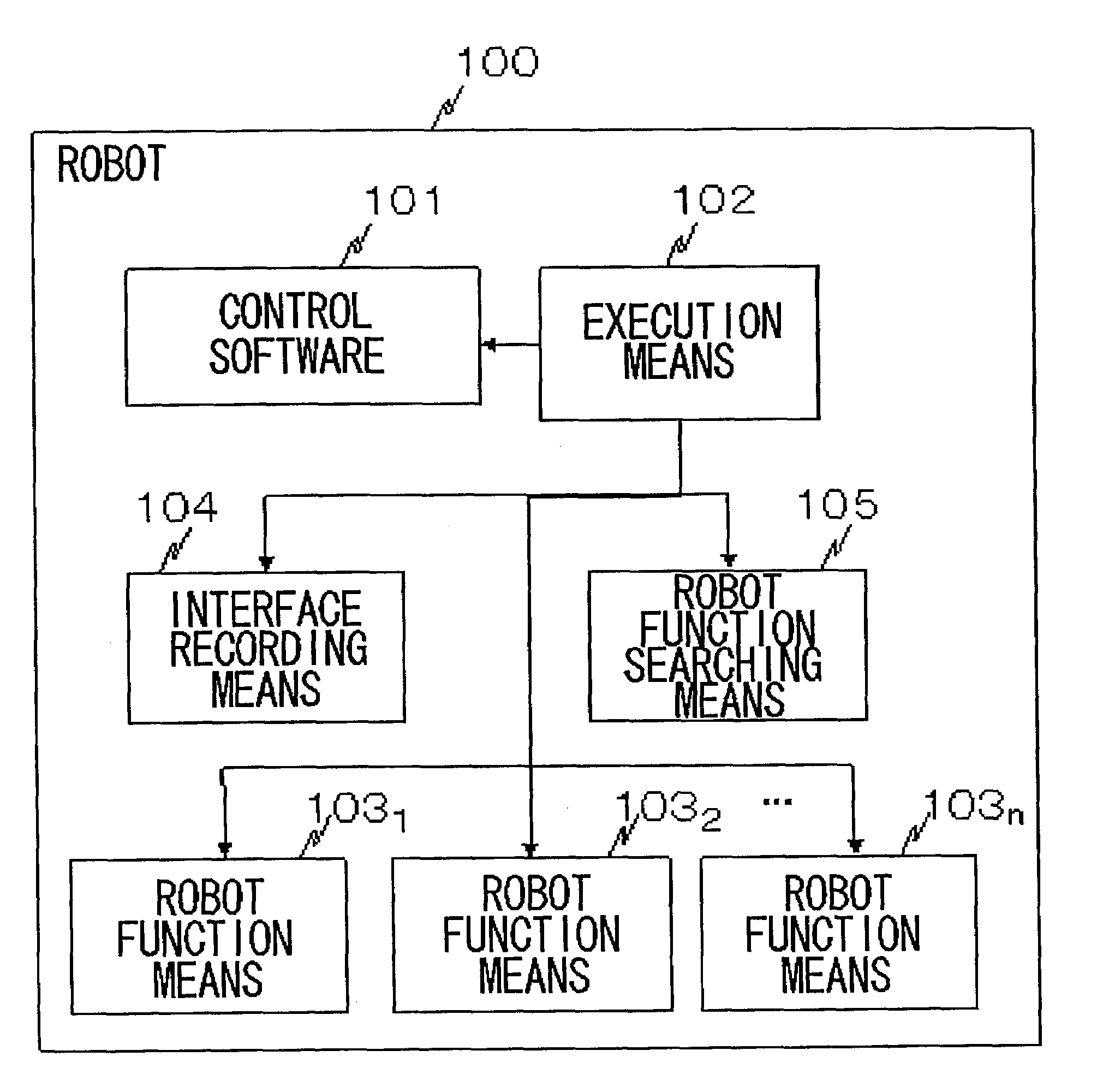
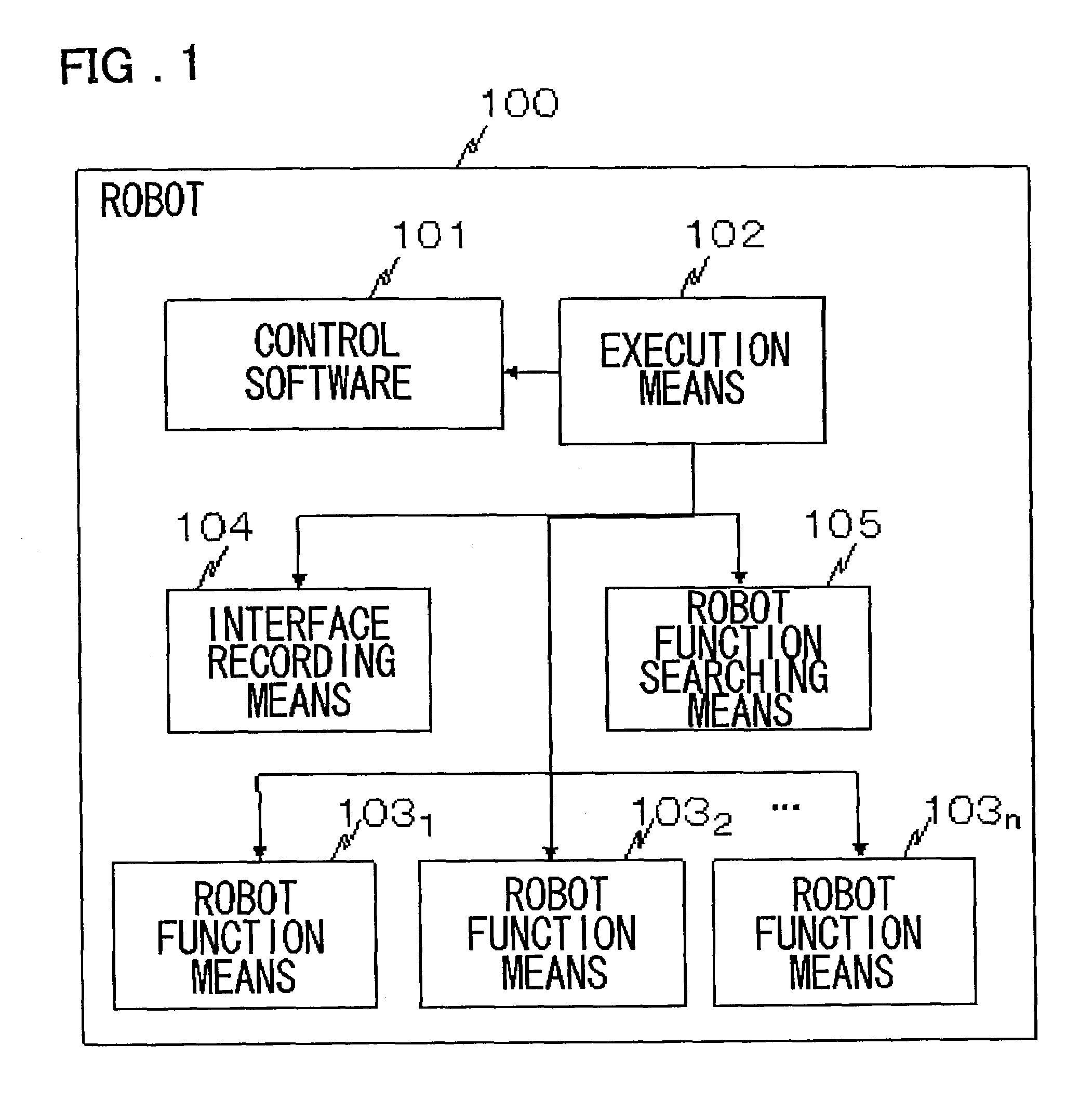
[0041]Next, embodiments of the present invention will be described in detail with reference to drawings. FIG. 1 is a block diagram showing a configuration of the present invention.

[0042]Referring to FIG. 1, a robot 100 according to a first embodiment of the present invention comprises control software 101, execution means 102 for executing commands of the control software 101 one after another, a plurality of robot function means 1031 to 103n for realizing respective motions of the robot 100, and interface recording means 104 for recording interface specifications of the robot function means 1031 to 103n, and robot function searching means 105 for determining robot function means that matches a request by the control software 101, using the interface recording means 104. The control software 101 is stored in storage means not shown, from which a command is read out, decoded, and executed by the execution means 102. The execution means 102 is included in a compile system where execut...

fourth embodiment

[0093]FIG. 5 is a block diagram showing a configuration of the present invention. Referring to FIG. 5, in this embodiment, a main body of the robot 100 includes the control software 101, control and execution means 102, and robot function searching means 105, and includes a main body part of the robot 100 and a plurality of detachable attached parts 110. The attached parts 110 are constituted by arms, feet, and a tail, for example. Incidentally, the detachable attached parts 110 may be a single part. The attached parts 110 include the interface recording means 104, and the robot function means 103 for realizing robot motions of the attached parts 110 in their insides. The robot function searching means 105 searches for interface specifications recorded in the interface recording means 104 of an attached part 110, in response to a request from the execution means 102.

[0094]In this embodiment, the interface specifications of the robot function means recorded in the interface recording...

seventh embodiment

[0100]FIG. 8 is a block diagram showing a configuration of the present invention. Referring to FIG. 8, in this embodiment, the main body of the robot 100 includes the control software 101, execution means 102, interface recording means 104, and robot function searching means 105, and includes the main body part of the robot 100 and a plurality of detachable attached parts 110. Each of the attached parts 110 includes robot function means 103. When an attached part 110 is attached to the main body of the robot, or at power-on, information on interface specifications of the robot function means 103 of the attached part 110 is registered in the interface recording means 104. When the attached part 110 is detached from the main body of the robot, control is exercised so that the information on the interface specifications stored in the interface recording means 104 is deleted from the interface recording means 104 or information indicating deletion (flag information) is added. The detach...


PUM


Abstract

System and method for allowing execution of control over robot hardware other than specific robot hardware by using control software that does not have features to be applied to the robot hardware other than the specific hardware designed for control. Control software makes an inquiry about the presence of robot function requested by control software through the use of interface recording and robot function searching. If it has been found that the robot function is present, there is a requests that robot motion be performed. If it has been found that the robot function is not present, the request is skipped, or the request is made to similar robot function.

Description

FIELD OF THE INVENTION[0001]The present invention relates to a robot control technique. More specifically, the invention relates to a system and a method for robot control that can be applied to different uses by replacement of control software, and a computer program product for executing robot control processing by a computer.BACKGROUND OF THE INVENTION[0002]Recently, robots that can realize different motions are widely used. In these robots, different motions can be realized by replacement of control software for controlling the robots. In an “AIBO” by Sony, which is a trademark of Sony, for example, different motions of the robot are enabled by equipping the robot with an external memory including an extension program. In a lot of robots at present, control software that fully matches hardware configurations of the robots is included. In the robot that has only arms and feet, for example, control software for controlling the motions of the arms and the feet is combined for use, ...

Claims


Application Information

Patent Timeline
Patent Type & Authority Patents(United States)
IPC IPC(8): G06F19/00B25J13/00B25J9/16B25J9/18G06F9/00G06F9/445G06F9/54G06F13/10
CPCB25J9/1602G05B2219/33053Y10S700/90G05B2219/33125G05B2219/39379G05B2219/33105Y02P90/02
Inventor TAKANO, YOSUKE
Owner NEC CORP
Why Eureka
Try Eureka