Eureka AIR delivers breakthrough ideas for toughest innovation challenges, trusted by R&D personnel around the world.

Vibration monitoring device and system

Inactive Publication Date: 2006-05-30
GELSOMINO JOSEPH
View PDF5 Cites 3 Cited by
  • Summary
  • Abstract
  • Description
  • Claims
  • Application Information

AI Technical Summary

Benefits of technology

[0010]The present invention comprises a system for monitoring the rotational stability of one or more rotating components in a water craft, generally comprising a cockpit mountable water resistant vibration monitoring device, vibration sensor means, means for transmitting data from said vibration sensor to said vibration monitoring u

Problems solved by technology

An acceptable amount of component vibration at one speed of rotation, may not be acceptable at other speeds of rotation, while changes in conditions of use and the stability of the machine containing the rotating component add further variation to vibration amounts.
Machinery contained in moving vehicles adds a level of difficult in ascertaining accurate measurement and evaluation of the rotating components particularly depending upon the environment within which the moving vehicle may be moving.
Vibrations associated with water craft, particularly vibrations in the motorized power train of small and medium sized water craft, are particularly difficult to accurately measure and assess, due to the continuing changing surface of water on which the vessel is traveling, and the interference occasioned by the inconsistent movement of the hull and power train in response to inconsistent wave action during the vessel's travel through water.
Thus vibrations which might foretell a potentially serious problem, may be felt only sporadically by a boat operator and in association with particular weather or wave impact and are easily dismissed as environmentally associated, as distinct from potential equipmen

Method used


Image

  • Vibration monitoring device and system
  • Vibration monitoring device and system

Examples


Example

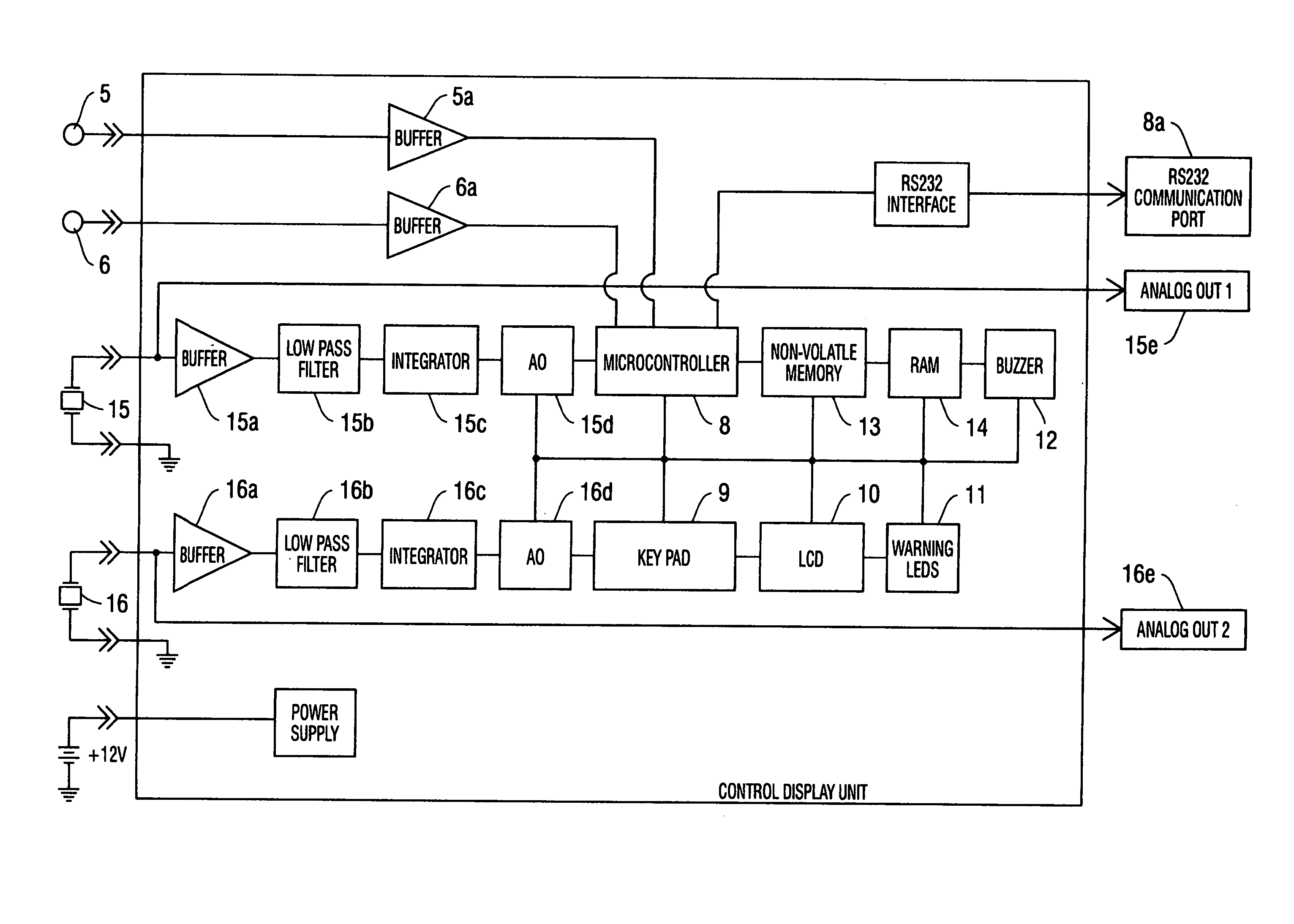
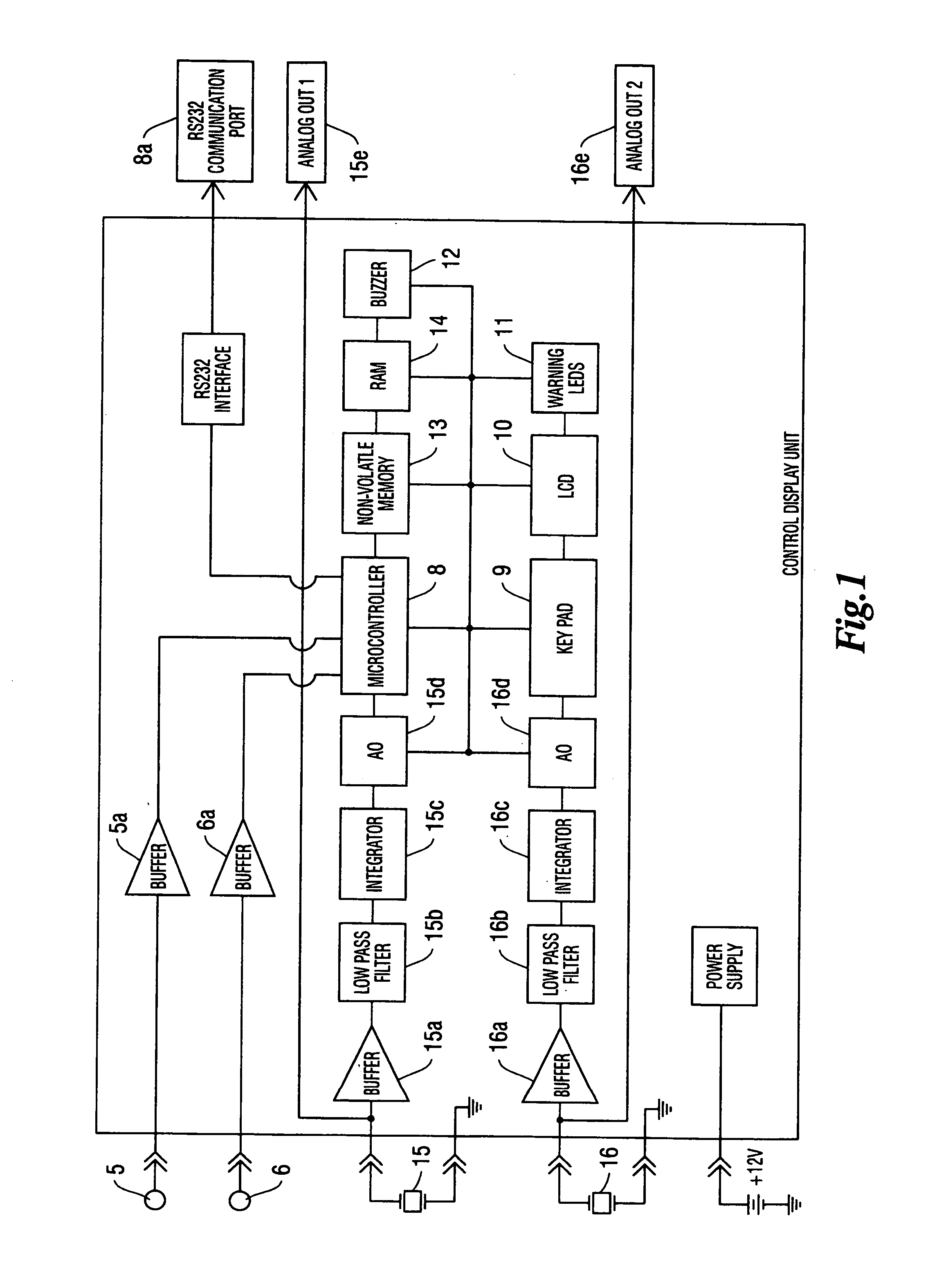
[0023]Therein, the rotational speed of a first discrete rotating shaft (not shown) of a device is sensed by a conventionally installed electronic tachometer 5, and the vibration of a controlling bearing supporting such first discrete rotating shaft is sensed by sensor 15 mounted at about said bearing. Signals generated by tachometer 5 are generally sent through a common buffer circuit 5a for input to micro-controller 8. Acceleration signals generated by sensor 15, are generally sent through a common buffer circuit 15a, signal filtering circuit 15b and integrator circuit 15c to analog / digital converter 15d. Integrator circuit 15c, changes the acceleration signal generated by sensor 15 and filtered by filter circuit 15b to a velocity signal for input to the analog / digital converter 15d. Port 15e is provided to enable further convenient access to data being generated by sensor 15 for use by other vibration sensing equipment. It should be understood that such port may also be arranged a...


PUM


Abstract

The present invention is a portable vibration monitoring device and system for evaluating the degradation of rotating components, the monitoring device being a portable electronic system which receives vibration and varying speed rotational data from one or more rotating components, converts the data to usable digital data, compares the sensed data to a pre-programmed normal model and provides a visual display of the stability characteristics of the rotating device to the operator for use in timely determining appropriate repairs.

Description

[0001]This application claims the benefit of Provisional application Ser. No. 60 / 425,447, filed Nov. 12, 2002.[0002]The present invention relates to a vibration monitoring device and system, which is particularly suitable for use with water going vessels having one or more rotating components which rotate at variable rotational speeds.BACKGROUND OF THE INVENTION[0003]Machines of all types and nature comprise components that rotate at varying speeds and which may vibrate with different amounts of vibration at different rotational speeds. An acceptable amount of component vibration at one speed of rotation, may not be acceptable at other speeds of rotation, while changes in conditions of use and the stability of the machine containing the rotating component add further variation to vibration amounts. There is therefore a continuing need for means for assessing and evaluating vibration with changes in speed of rotation and particularly assessing and evaluating changes in vibration as t...

Claims


Application Information

Patent Timeline
IPC IPC(8): G01V1/40G01H1/00G01M13/02
CPCG01M13/028G01H1/003
Inventor GELSOMINO, JOSEPH
Owner GELSOMINO JOSEPH
Why Eureka
Eureka Blog
Learn More