Heat pump clothes dryer

a heat pump and dryer technology, applied in the field of dryers, can solve the problems of the least expensive and the most fallacious way to build a dryer, and achieve the effect of improving performance and efficiency

Inactive Publication Date: 2006-06-06
FLI HLDG COMPANY
View PDF11 Cites 205 Cited by
  • Summary
  • Abstract
  • Description
  • Claims
  • Application Information

AI Technical Summary

Benefits of technology

[0004]Accordingly, it is an object of the present invention to provide a dryer which has improved performance and efficiency.

Problems solved by technology

This is the simplest, least expensive, and the most fallacious way to build a dryer.

Method used


Image

  • Heat pump clothes dryer
  • Heat pump clothes dryer
  • Heat pump clothes dryer

Examples


Embodiment Construction

)

Heat Pump Dryer

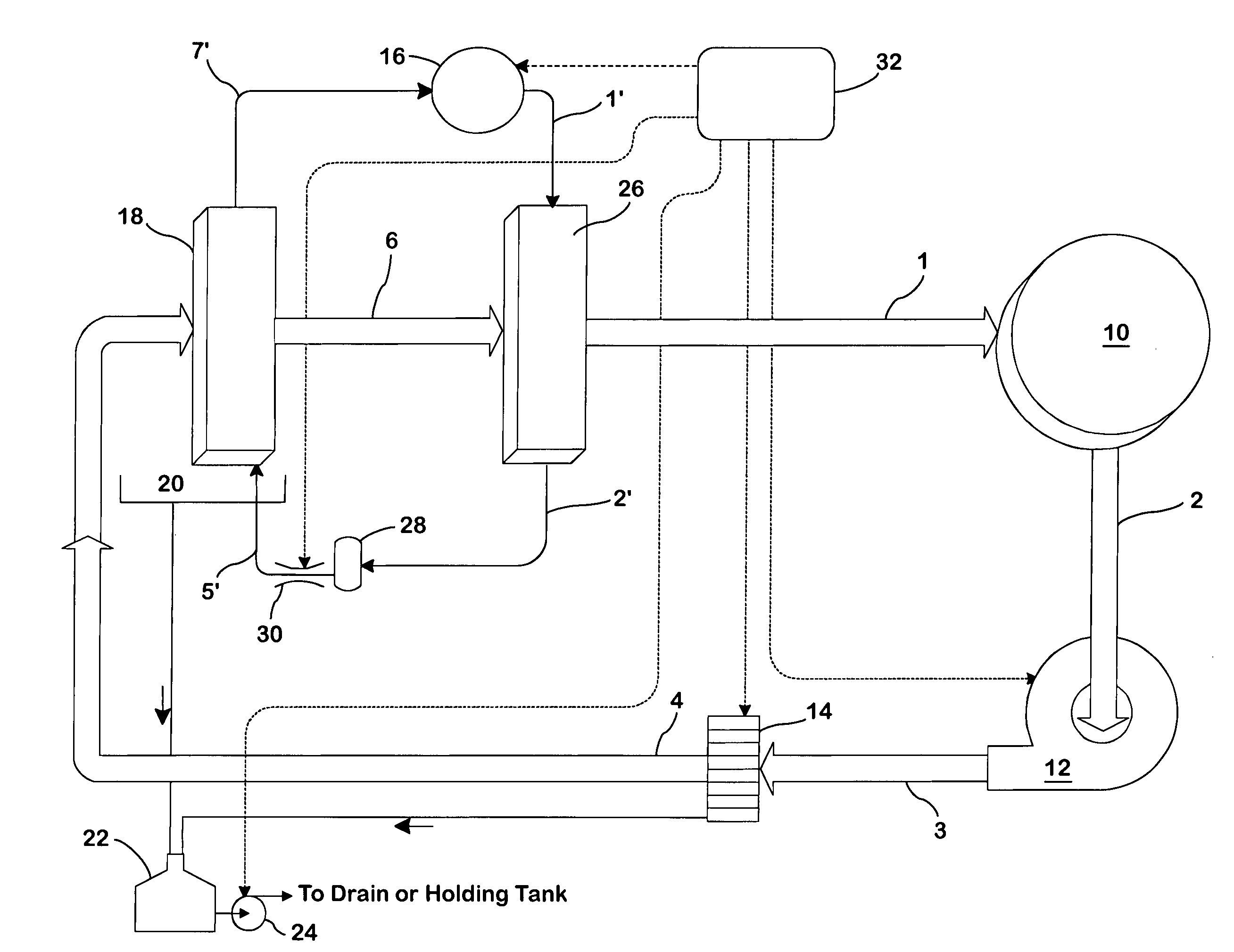
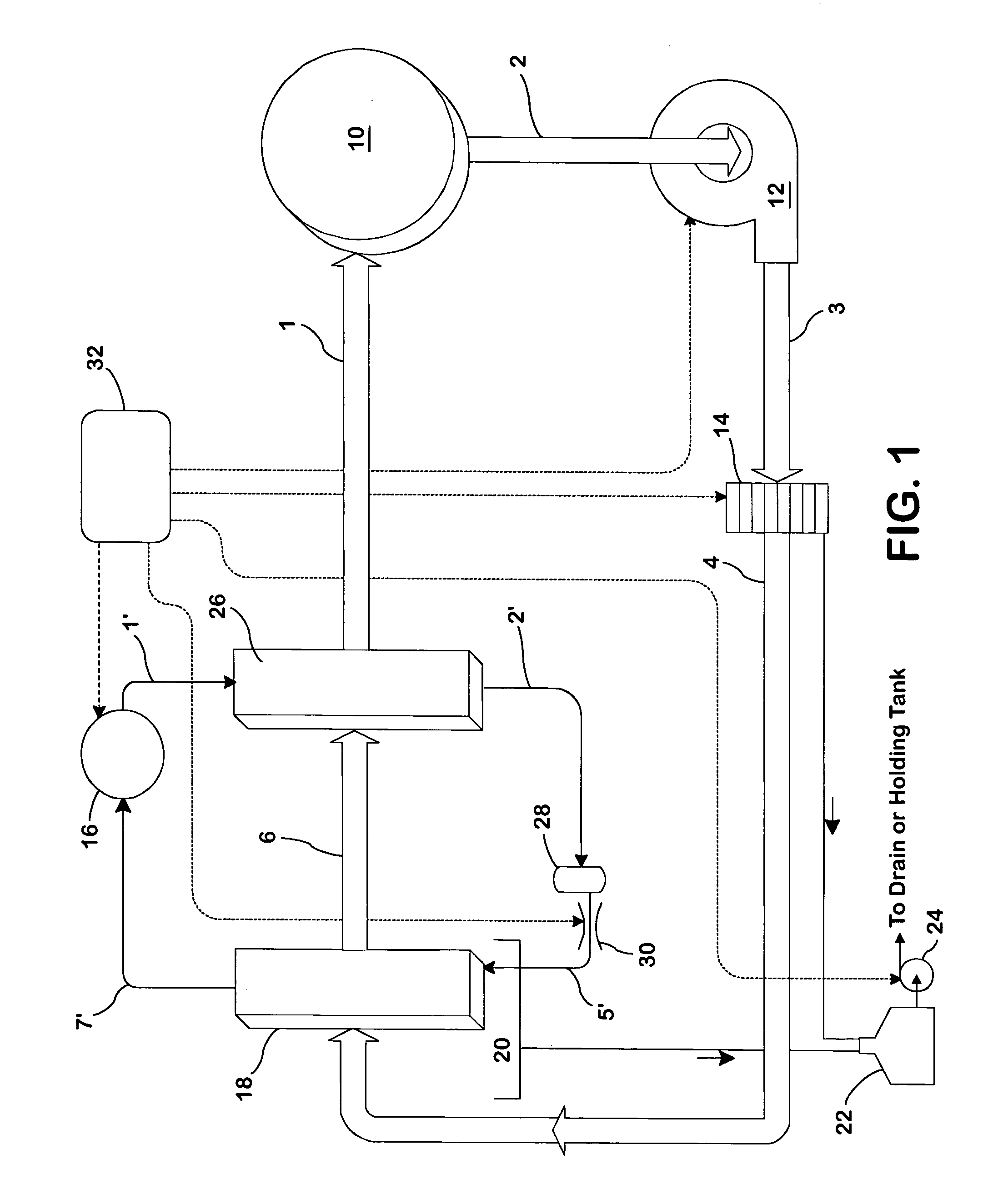
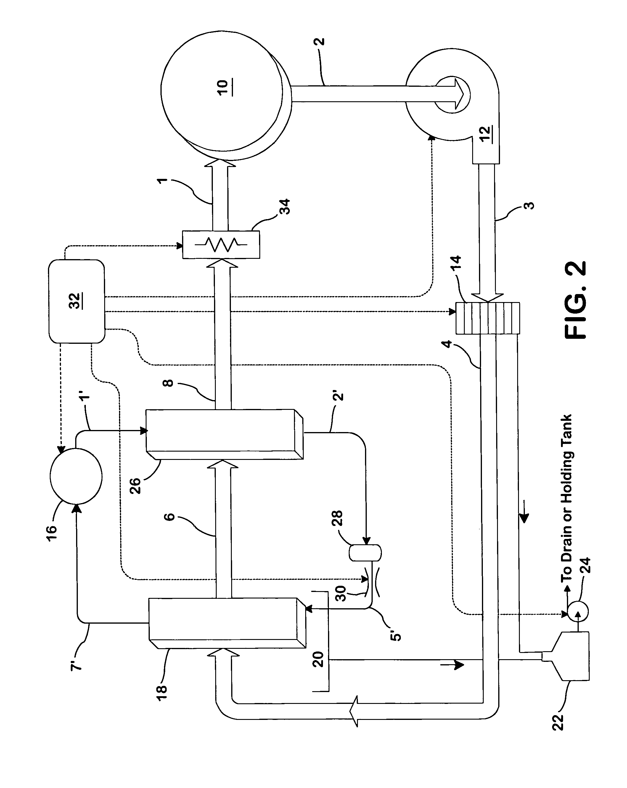
[0052]Inside the drum, the basic heat pump dryer functions in the same way as a conventional dryer. Heated dry air enters the drum, extracts moisture from the clothes, and then leaves the drum, cooler and wetter. The fundamental difference is in the way the heat pump dryer provides the heated dry air.

[0053]Instead of continually heating room air and then venting it, the heat pump dryer dries and warms the air from the drum exhaust, and returns it to the drum. Useful heat is recovered and reused instead of being vented out of the building.

[0054]This is accomplished by connecting the drum exhaust back to the drum intake, through dehumidifier means. The heat pump dryer uses a closed air loop, with dehumidifier means in the flow path. The dehumidifier means removes entrained moisture from wet air exiting the drum, reheats the air, and returns it to the drum. The drum is a rotating drum which may be rotated by any suitable means known in the art.

[0055]With reference to FI...


PUM


Abstract

A drying apparatus for drying articles such as clothing is provided. The drying apparatus includes a chamber for containing articles to be dried and a system for supplying heated dry air at a first temperature to the chamber. The air supplying system comprises an air flow pathway having an evaporator for removing moisture from air exiting the chamber and for decreasing the temperature of the air to below dew point temperature. The air supply system further has a condenser for increasing the temperature of the air exiting the evaporator to the first temperature. The drying apparatus further has a heat pump system having a refrigerant loop which includes a compressor, the condenser, a TEV valve, and the evaporator.

Description

CROSS-REFERENCE TO RELATED APPLICATION[0001]Benefit is claimed of U.S. Provisional Patent Application 60 / 507,466, filed Sep. 29, 2003 and entitled “HEAT PUMP CLOTHES DRYER”, the disclosure of which is incorporated by reference herein as if set forth at length.BACKGROUND OF THE INVENTION[0002]The present invention relates to a dryer for drying clothes and other things made from fabric and to a washer for washing same.[0003]Ordinary dryers are a study in simplicity. As shown in FIG. 30, they draw room air, pass it over a heater, and blow it through a rotating drum containing laundry to be dried. The air passes through the drum once, and is then vented out of the building. Some of the air extracts moisture from the fabric, and some of it bypasses the laundry, and escapes without doing any work. This is the simplest, least expensive, and the most fallacious way to build a dryer.SUMMARY OF THE INVENTION[0004]Accordingly, it is an object of the present invention to provide a dryer which h...

Claims


Application Information

Patent Timeline
Patent Type & Authority Patents(United States)
IPC IPC(8): F26B5/08D06F58/20
CPCD06F58/206D06F25/00D06F58/22D06F58/04D06F34/26D06F2105/20D06F2103/36D06F2103/32D06F2105/36D06F2103/34
Inventor GOLDBERG, MICHAELTRUMAN, JAMES C.KNIFFIN, ALEXANDER B.
Owner FLI HLDG COMPANY
Why Eureka
Try Eureka