Fluid level measuring device

a technology of fluid level and measuring device, which is applied in the direction of liquid/fluent solid measurement, machines/engines, instruments, etc., can solve the problems of interlocking the lugs with the slots in the handle, and achieve the effect of improving sealing capability, constant pressurization, and positive locking featur

Inactive Publication Date: 2006-06-06
FURON
View PDF106 Cites 23 Cited by
  • Summary
  • Abstract
  • Description
  • Claims
  • Application Information

AI Technical Summary

Benefits of technology

[0010]The bayonet interconnection in unison with the gasket supplies an actual pressurized seal not found in any of the prior art assemblies thereby allowing pressurized testing of the combustion engine, transmission, or other machinery without either removal of the dipsick or attempts at sealing the dipstick. Furthermore, a sealed dipstick allows the combustion engine, transmission, or other machinery to run at the intended pressure rather than either below the intended pressure or at the intended pressure due to an adjustment.
[0011]The structure is manufactured from lightweight, corrosion-resistant, plastic materials with the exception of the flexible metallic shaft, attachment fitting, blade, and metal engine fitting. The seal and locking engagement between the handle and enlarged end preferably involves a quarter-turn sealing motion with an improved sealing capability and a positive lock feature.
[0012]It is an object of the invention to provide a fluid level indicating system capable of being in fluid communication with the combustion engine, transmission, or other machinery to which it i

Problems solved by technology

This causes interengagement of t

Method used


Image

  • Fluid level measuring device
  • Fluid level measuring device
  • Fluid level measuring device

Examples


Embodiment Construction

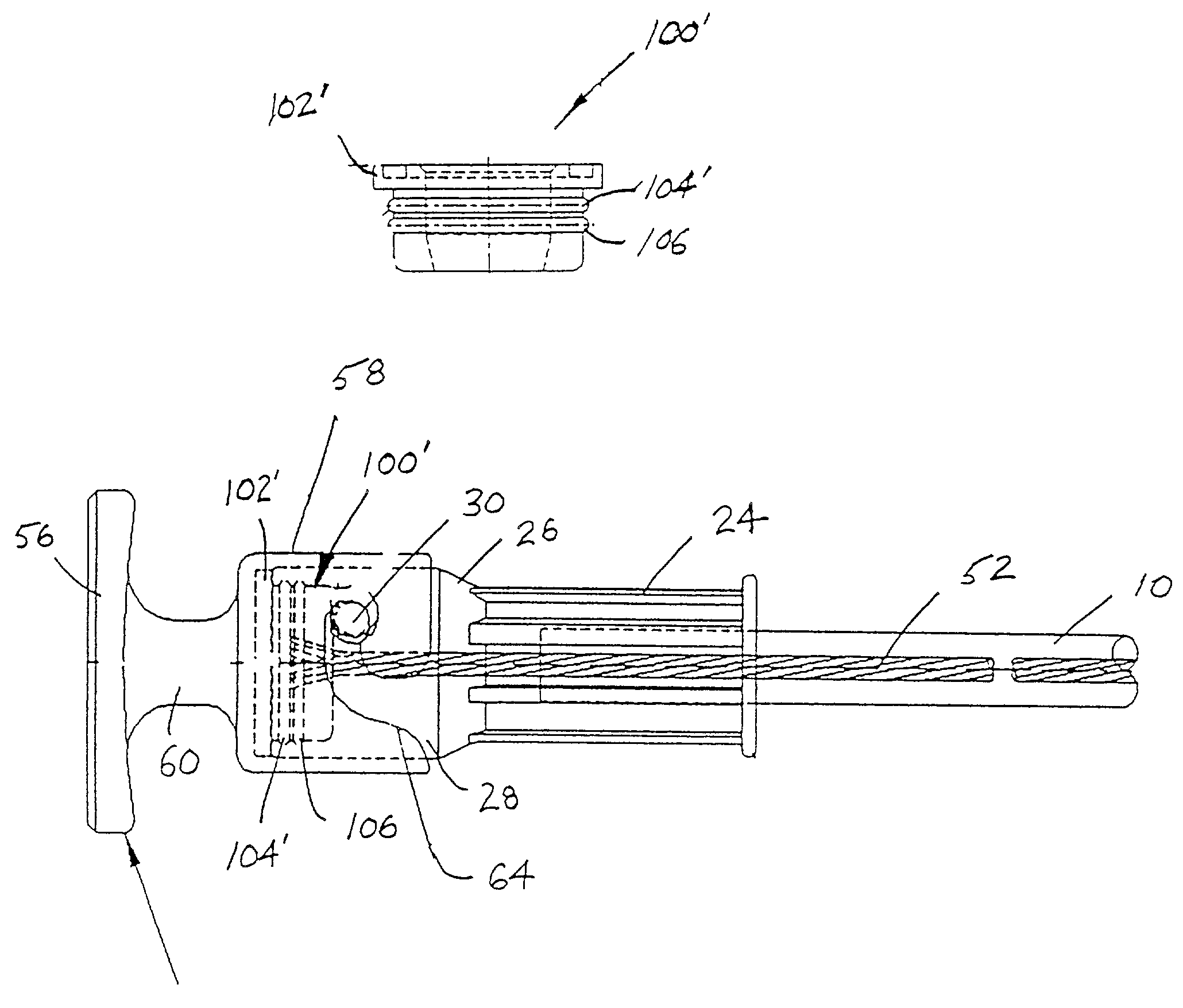
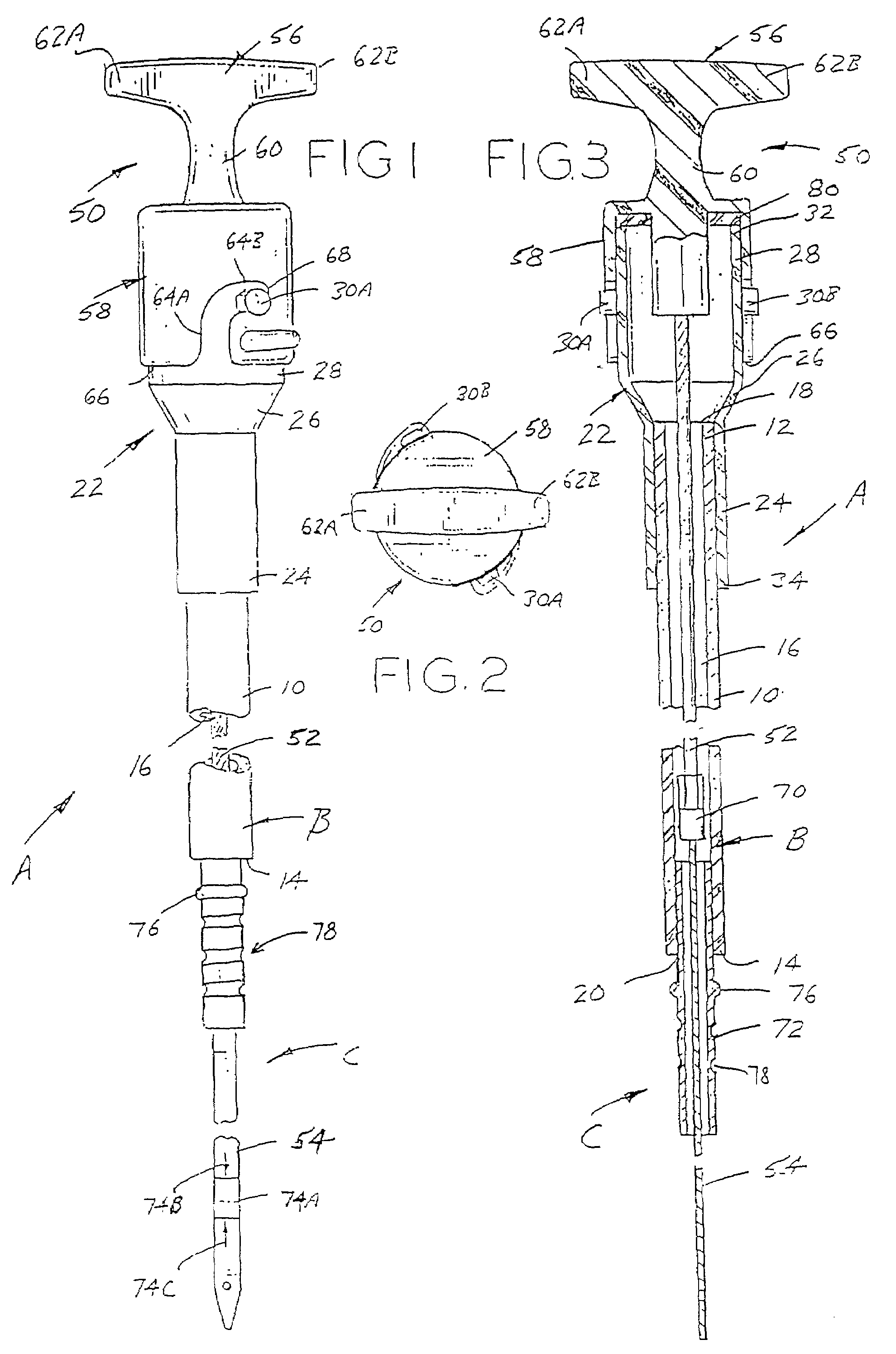
[0025]Referring now to the drawings wherein the showings are for the purposes of illustrating the preferred embodiments of the invention only and not for purposes of limiting the invention, the overall arrangement of the preferred construction of the fluid level measuring device A can best be understood by reference to FIGS. 1 and 3. As illustrated therein, the fluid level measuring device A comprises a stationary tube assembly B with a dipstick assembly C removably disposed therein. Specifically, tube assembly B is an elongated, hollow guide tube 10 with first and second spaced ends 12 and 14 having a through passage 16 that communicates with first and second openings 18 and 20 at the respective first and second ends.

[0026]The tube assembly B further includes an enlarged diameter coupler or spout 22 attached to the first end 12 of the guide tube 10. In a preferred embodiment, the coupler is joined to the first end 12 of the guide tube as described herein. The coupler 22 has a small...


PUM


Abstract

A fluid level measuring device, also referred to as a dipstick, for measuring the fluid level in a fluid reservoir or tank, such as an oil pan or transmission reservoir in an internal combustion engine. The fluid level measuring device includes a stationary tube assembly in which a dipstick assembly is disposed. The dipstick assembly includes a fluid level indicator measuring blade attached to an elongated shaft which is directly molded into a plastic handle assembly. The plastic handle assembly includes a bayonet type locking mechanism for locking the handle to the stationary tube assembly. A compressible seal forms a pressurized seal between the stationary tube assembly and the handle.

Description

BACKGROUND OF THE INVENTION[0001]The subject matter herein is a continuation of previously filed U.S. patent application Ser. No. 09 / 947,314, filed on Sep. 7, 2001 now U.S. Pat. No. 6,453,740 and Ser. No. 08 / 976,781, filed Nov. 24, 1997, now U.S. Pat. No. 6,314,808 B1, which is a continuation in part of U.S. patent application Ser. No. 08 / 607,690, filed on Feb. 27, 1996, now abandoned.[0002]The subject invention is directed to a device used to measure fluid levels, and more particularly, to dipsticks used to measure fluid levels by immersing an indicator at one end of the dipstick into a fluid holding compartment.[0003]With internal combustion engines, transmissions, and other machinery requiring fluids for lubrication and cooling, it is known to use a fluid measuring device for indicating the fluid level in a selected fluid holding compartment. Typically, the fluid measuring device is a dipstick for checking the level of fluid such as engine or transmission oil, or hydraulic fluid ...

Claims


Application Information

Patent Timeline
IPC IPC(8): G01F23/00G01B3/00G01F23/04
CPCG01F23/04
Inventor WILLIAMS, ANTHONY J.HICKS, KAREN S.WIANDT, DAVID A.JUSTICE, DANIEL S.SHRIBER, BRIAN G.
Owner FURON
Why Eureka
Try Eureka