Temperature maintaining apparatus and temperature control apparatus and method therefor

a technology of maintaining apparatus and temperature control apparatus, which is applied in the direction of lighting and heating apparatus, heating types, instruments, etc., can solve the problems of unsatisfactory performance, low and high temperature, and the temperature of the air in the vehicle drops to an uncomfortable level, so as to reduce the number of parts required, increase the degree of comfort, and reduce the effect of the number of parts

Inactive Publication Date: 2006-06-06
MARINE CANADA ACQUISITIONS INC
View PDF42 Cites 10 Cited by
  • Summary
  • Abstract
  • Description
  • Claims
  • Application Information

AI Technical Summary

Benefits of technology

[0025]The invention offers significant advantages compared to the prior art, particularly prior art heaters and other heat transfer devices which control temperature by switching on and off at fixed temperature values. By comparison the invention allow such a device to adapt to changing ambient conditions. If temperatures fall, then a heating device, for example, tends to operate longer until the temperature reaches a set upper value. This lengthened period of time is sensed by the invention and the temperature where the heater becomes operational is raised. This typically causes the heater to cycle on and off at an increased frequency. The effect is to maintain the mean temperature and give an increased degree of comfort compared with a conventional system.
[0026]At the same the invention allows such heat transfer devices to adapt in other ways. For example, a prolonged period of cooling may be sensed and the heater may be turned on even though the temperature has not fallen to a value which would normally trigger operation of the heater. This again maintains a minimum mean temperature and increases the degree of comfort.
[0027]The invention also permits a single temperature sensor to replace two different temperature sensors normally used for temperature regulation and for sensing an overheat condition. This reduces the number of parts required for devices such as transit heaters and simplifies assembly.
[0028]The invention offers significant advances and increases adaptability of various heat transfer devices such as heaters and hot liquid transit heaters in particular. For example, where such a heater has two different heat sensors the system can operate without information on which sensor is which or in which direction liquid flows through the heater. Moreover, if one sensor is removed, or one becomes faulted, then the system can adapt and still operate correctly.

Problems solved by technology

This cycling on and off between preset lower and higher temperatures produces less than satisfactory performance under some conditions.
People in a transit vehicle, for example, may perceive that the temperature of the air in the vehicle drops to an uncomfortable level when the heater cycles on and off between preset lower and upper temperatures.
This is because too much time may occur near the bottom of the cycle when the temperature is low and / or because the mean temperature is reduced below optimum levels.
Standard on / off temperature controls or thermostats are not capable of adjusting themselves to such a situation.
The need for two different sensors increases the cost and complexity of the units.
Conventional transit vehicle heaters do not readily adapt to a reversal of liquid flow because of temperature sensors placed adjacent the fluid inlet and fluid outlet.
The heater controls are adversely affected when the fluid flow is reversed because of the effect this has on the readings of the sensors.
Also some conventional heaters require two sensors adjacent the fluid inlet and fluid output respectively and cannot operate with a single sensor or with one of the sensors disabled.
The controls have a lack of flexibility in this respect.

Method used


Image

  • Temperature maintaining apparatus and temperature control apparatus and method therefor
  • Temperature maintaining apparatus and temperature control apparatus and method therefor
  • Temperature maintaining apparatus and temperature control apparatus and method therefor

Examples


Embodiment Construction

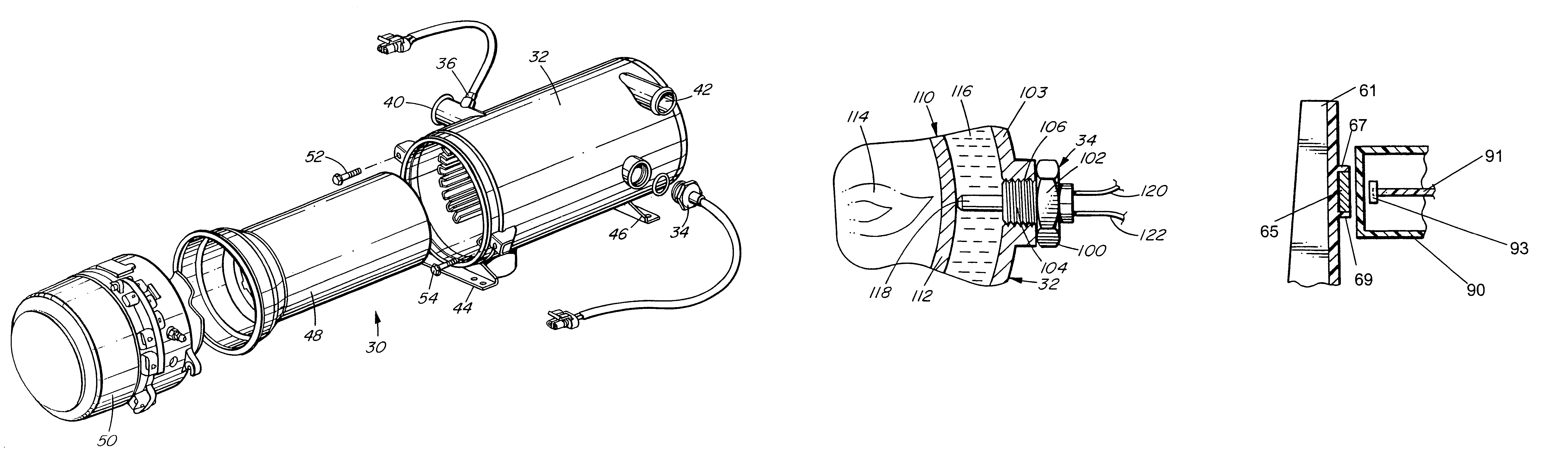
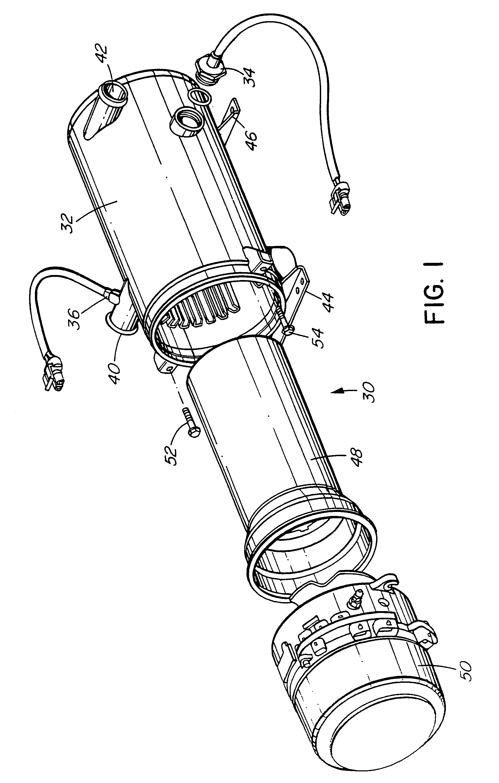
[0059]Referring to the drawings, and first to FIG. 1, this shows a transit heater 30 according to an embodiment of the invention. The heater includes a heat exchanger 32 equipped with a primary temperature sensor 34 and a secondary temperature sensor 36. The latter is optional as described below. There are fittings 40 and 42 which serve as inlets and outlets for liquid, a mixture of water and anti-freeze being the usual liquid for a transit vehicle heater. Mounting brackets 44 and 46 are connected to the heat exchanger for mounting the heater on a transit vehicle or similar application. A combustion tube 48 fits within the heat exchanger and a burner head assembly 50 fits over the combustion tube. The assembly is secured to the heat exchanger by bolts 52 and 54.

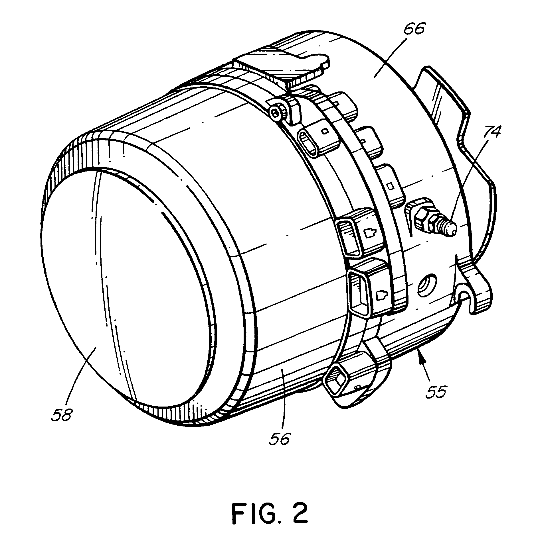
[0060]The burner head assembly is shown in better detail in FIGS. 2 and 3. The assembly includes a burner head assembly housing 51, cylindrical in this example, having two portions, a blower housing 56 and a head flange assem...


PUM


Abstract

A method and apparatus are provided for maintaining a temperature between a first value and a second value. The method and apparatus utilize a heat transfer device capable of cycling through a series of cycles, the device being capable of changing the temperature from the second value to the first value when operational. During each cycle the device transfers heat for a first period of time when the temperature reaches the second volume until the first value is reached and thereafter the device stops transferring heat. The first period of time is compared to a desired cycle-on period of time during each cycle and the second temperature value then is adjusted for a subsequent cycle of the device so the first period of time when the device transfers heat approaches the desired cycle-on period of time. There may also be provided temperature controls for a liquid heater having a jacket containing the liquid. The jacket has an inner heated wall and an outer wall spaced apart from the inner wall. The controls include a temperature sensor capable of fitting to the jacket so that the sensor contacts the inner wall and the liquid. A control module monitors temperature sensed by the temperature sensor. The control module causes the heater to stop heating when the temperature is heated by the heater to a first value and causes the heater to heat when the liquid cools to a second value lower than the first value. The control module senses overheating when temperature sensed by the sensor increases to a third value, higher than the first value, when the heater is not heating, and then causes the heater to shut down.

Description

[0001]This is a divisional application of U.S. patent application Ser. No. 10 / 195,145, filed Jul. 15, 2002 now U.S. Pat. No. 6,766,962.BACKGROUND OF THE INVENTION[0002]This invention relates to temperature maintaining apparatuses such as transit vehicle heaters and temperature control apparatuses and methods therefor.[0003]Various temperature maintaining apparatuses, particularly heaters, operate in a cyclic fashion. When the temperature reaches a certain threshold, such apparatuses operate for a period of time until the temperature is brought to a certain level and thereafter the apparatus becomes nonoperational until the threshold is reached again. For example, in a heater the temperature may be the temperature of a fluid and the heater operates when the temperature of the fluid drops to a set lower value. The heater continues to operate until the temperature is raised to a higher level at which time the heater switches off until the temperature again drops to the lower level.[000...

Claims


Application Information

Patent Timeline
Patent Type & Authority Patents(United States)
IPC IPC(8): B60H1/02G05D23/19
CPCG05D23/1951G05D23/1917
Inventor PAUL, DOUGLAS THOMPSONYOUNG, JONATHANFACCONE, ANGELO
Owner MARINE CANADA ACQUISITIONS INC
Why Eureka
Try Eureka