Illuminator and projector

a projector and projector technology, applied in the field of illumination and projectors, can solve the problems of serious illumination unevenness, undesirable influence on adjacent optical components, etc., and achieve the effect of improving expressiveness of a dark portion, stably adjusting, and enhancing the contrast of the projected imag

Active Publication Date: 2006-06-06
SEIKO EPSON CORP
View PDF7 Cites 42 Cited by
  • Summary
  • Abstract
  • Description
  • Claims
  • Application Information

AI Technical Summary

Benefits of technology

[0009]An object of the present invention is to provide an illuminator capable of enhancing the contrast of an image even when a lamp such as a high-pressure mercury lamp with little variation in illuminating light volume is used, and a projector having the illuminator.
[0010]Another object of the present invention is to provide an illuminator that is scarcely influenced by the heat generated when the intensity of the illumination light is adjusted over a wide range and is unlikely to cause illumination unevenness.

Problems solved by technology

On the other hand, when the light from the light source is extremely attenuated using the optical lens stop shown in the Japanese Patent Laid-Open Publication No. 2002-23106, a heat is generated and concentrated on the optical lens stop, which can exert undesirable influence on the adjacent optical components or the like.
Further, when the optical lens stop is used to extremely attenuate the light from the light source to 30 to 40%, unevenness of illumination may become prominent on account of minute errors in disposition of the components such as a lamp, a light shield and an integrator, which may cause serious illumination unevenness by exchanging the lamp etc.

Method used


Image

  • Illuminator and projector
  • Illuminator and projector
  • Illuminator and projector

Examples


first embodiment

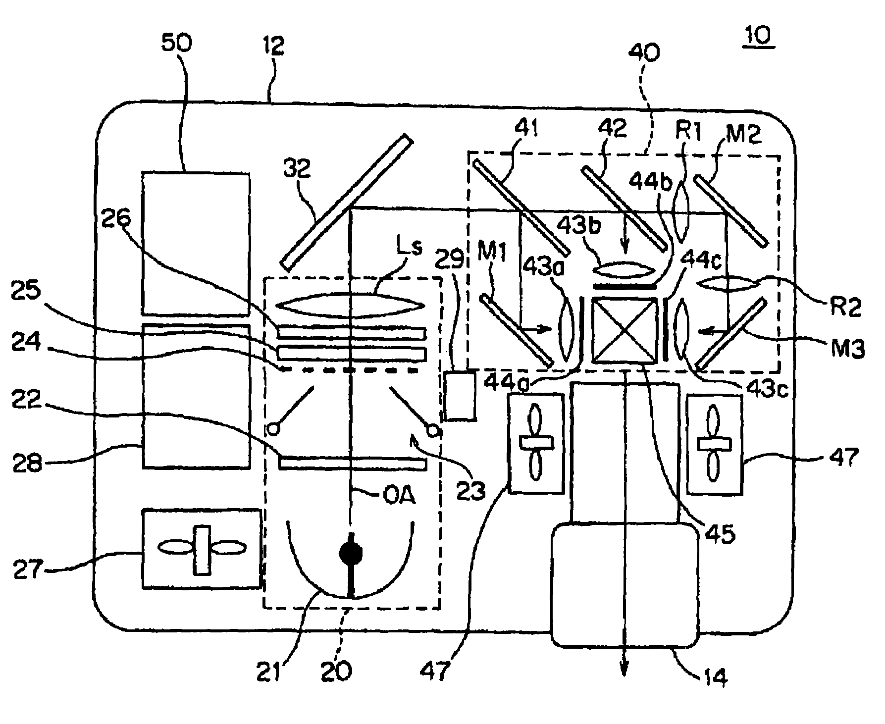
[0071]An example of the operation of the projector 10 will be described below. When a video signal is inputted to the projector 10 through a video input terminal, the image-analyzing circuit 61 detects the luminance peak value of the image and outputs the value to the CPU 71. The downstream resizing circuit 62 appropriately converts the resolution of the video signal to fit to the pixel number of the light valve 44a (44b, 44c). The gain-adjusting circuit 63 adjusts the luminance signal in the video signal based on the command by the CPU 71. The CPU 71 determines a gain adjustment on the basis of the luminance peak value of the image obtained by the image-analyzing circuit 61 and outputs the result to the gain-adjusting circuit 63. For instance, when the luminance peak value Ip of the image is 50% of the upper limit Imax of the luminance capable of being inputted to the projector 10, the gain-adjustment amount AG is doubled. In this case, the illuminating light volume of the light v...

second embodiment

[0073]Second Embodiment An illuminator according to the present invention will be described below. The illuminator of the second embodiment drives the open / close light shield 23 at six or less rotation angle stages. When the motors 29b and 29c provided on the open / close light shield 23 is constructed by a step motor, though the rotation angle of the light-shielding plate 23a and 23b can be precisely controlled, much cost is required for the motor. Specifically, in order to secure sufficient resolution of luminance modulation, the step angle of the step motor has to be set approximately at one degree or a mechanism such as a reduction gear has to be provided, which can be an obstacle for producing a small and inexpensive illuminator. Accordingly, in the present embodiment, the light-shielding plates 23a and 23b are directly driven by a relatively inexpensive step motor with the step angle of about ten degrees or more.

[0074]Following Table 2 is an allocation table partially extracted ...

third embodiment

[0076

[0077]An illuminator according to a third embodiment of the present invention will be described below. The illuminator of the third embodiment is a modification of the illuminator of the second embodiment.

[0078]FIG. 7 is a graph showing the relationship between each rotation angle of the light-shielding plates 23a and 23b of the open / close light shield 23 and the illumination intensity (adjusted amount) at the time. As clearly shown in the curve of the graph, the illumination intensity is not regularly decreased in accordance with the increase in the rotation angle, but the angle range with small fluctuation, i.e. inclination, of the illumination intensity and the angle range with great fluctuation are alternately repeated. In other words, the curve represents the light-attenuation rate changing stepwise in accordance with the rotation angle. This is because the light beam from the first fly's eye lens 22 passes through between the light-shielding plates 23a and 23b while conve...


PUM

PropertyMeasurementUnit
step angleaaaaaaaaaa

Abstract

When a video signal is inputted to a projector (10) through a video input terminal, a luminance peak value of an image of the video signal is detected by an image-analyzing circuit (61) to be outputted to a CPU (71). A gain-adjusting circuit (63) adjusts a luminance signal in the video signal based on a command from the CPU (71). The CPU (71) determines a gain adjustment amount based on the luminance peak value of the image obtained by the image-analyzing circuit (61) and outputs the result to the gain-adjusting circuit (63). For instance, when the luminance peak value (Ip) of the image is 50% of the upper limit (Imax) thereof, a gain-adjusting amount AG is doubled. In this case, an illuminating light volume of a light valve (44a) has to be reduced to 50%, which is achieved by light-attenuation by a light-source lamp (21) and an open / close light shield (23).

Description

BACKGROUND OF THE INVENTION[0001]1.Technical Field of the Invention[0002]The present invention relates to an illuminator and a projector using the illuminator.[0003]2.Description of Related Art[0004]An effort has been made to enhance the contrast of an image of a projector by controlling an emitting light volume of a metal halide lamp, i.e. a light source, in accordance with the average illuminance of the image (see Japanese Patent Laid-Open Publication No. Hei 5-66501).[0005]Alternatively, instead of varying the emitting light volume of the light source, the light volume is adjusted by an optical lens stop to enhance the contrast of the image (see Japanese Patent Laid-Open Publication No. 2002-23106).[0006]However, the majority of projectors nowadays use a high-pressure mercury lamp as the light source. When the emitting light volume of such a high-pressure mercury lamp is adjusted in the same manner as described in the Japanese Patent Laid-Open Publication No. Hei 5-66501, the 100...

Claims


Application Information

Patent Timeline
Patent Type & Authority Patents(United States)
IPC IPC(8): G03B21/14F21V1/06G02B26/02G03B21/16G03B21/20G03B21/26H04N5/74G02F1/13357F21V11/18G02B26/00G02F1/133G03B21/00G03B21/18
CPCG03B21/18
Inventor MOMOSE, AKIRAMIYAZAWA, ATSUSHINAITO, KEIJIRO
Owner SEIKO EPSON CORP
Why Eureka
Try Eureka