Control method of sliding a vehicle door by a powered sliding device

Inactive Publication Date: 2006-06-06
MITSUI KINZOKU ACT
View PDF8 Cites 7 Cited by
  • Summary
  • Abstract
  • Description
  • Claims
  • Application Information

AI Technical Summary

Benefits of technology

[0006]Therefore, it is an object of the present invention to prevent the unnecessary time lag by switching the use and the nonuse of the annunciation buzzer by

Problems solved by technology

On the contrary, it is impossible to expect when and under which con

Method used


Image

  • Control method of sliding a vehicle door by a powered sliding device
  • Control method of sliding a vehicle door by a powered sliding device
  • Control method of sliding a vehicle door by a powered sliding device

Examples


Embodiment Construction

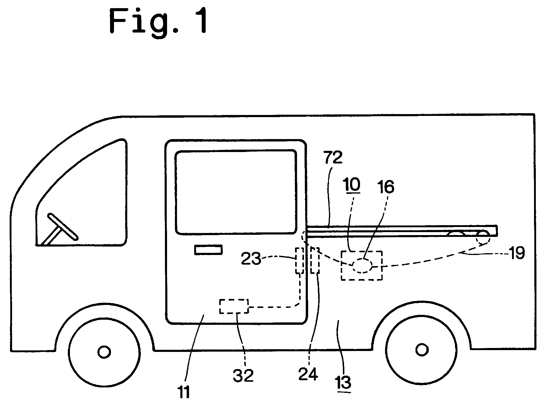
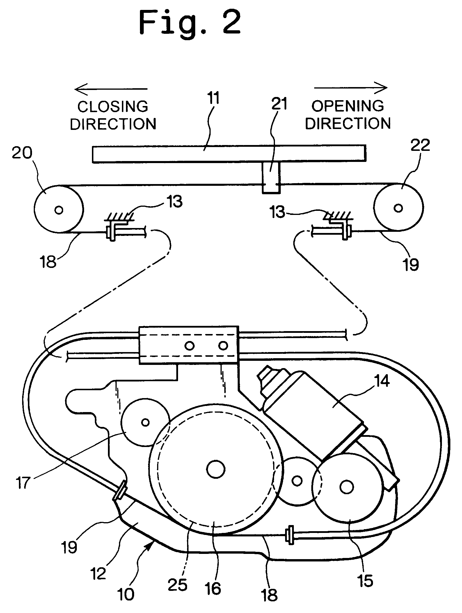
[0013]One preferred embodiment of the present invention will be described by using drawings. FIG. 1 shows the rough relation between a powered sliding device 10 according to the present invention and a vehicle sliding door 11 which slides in the door closing direction and in the door opening direction by the powered sliding device 10, and FIG. 2 shows the expanded relation between both.

[0014]The sliding door 11 is slidably attached to a vehicle body 13, and is slidable in the back and forth direction of the vehicle body 13 along a guide rail 72 provided to the vehicle body 13. A base plate 12 of the powered sliding device 10 is fixed to the vehicle body 13, and the base plate 12 is provided with a motor 14, a reduction mechanism 15, a wire drum 16, and an electromagnetic brake 17. The electromagnetic brake 17 operates by the electric control to brake the wire drum 16.

[0015]To the wire drum 16, one end sides of two wire cables 18, 19 are connected. The other end side of the first wir...


PUM


Abstract

A control method wherein sliding of a sliding door by a powered sliding device is started after sounding an annunciation buzzer when an operating switch is operated, but when a remote control transmitter integrally having an ignition key is operated, the sliding of the sliding door by the powered sliding device is started without operating the annunciation buzzer.

Description

BACKGROUND OF THE INVENTION[0001]1. Field of the Invention[0002]The present invention relates to a control method of sliding a vehicle door by a powered sliding device.[0003]2. Description of the Related Art[0004]Previously, a powered sliding device for a vehicle sliding door has been well known, which slides the sliding door in the door closing direction and door opening direction by rotating a wire drum connected through a wire cable to the sliding door by the power of a motor. The sliding device is started by the operation of an operating switch in the vehicle or a remote control transmitter.[0005]Among the sliding devices, there are some where it is set to sound a buzzer for calling the attention of the persons concerned when receiving an operating signal from the operating switch or the remote control transmitter. In the case of a sliding device of this kind, the start of sliding of the sliding door is delayed by the operating time of the buzzer (about 0.5 sec).SUMMARY OF THE I...

Claims


Application Information

Patent Timeline
IPC IPC(8): B60L1/00B60J5/04E05B65/08E05F15/70
CPCE05B81/20E05B83/04E05B65/08E05Y2201/21E05Y2201/654E05F15/70E05Y2900/531E05Y2400/814E05F15/646E05Y2201/664
Inventor YOKOMORI, KAZUHITO
Owner MITSUI KINZOKU ACT
Why Eureka
Try Eureka