Optical filtering by using an add-drop node

a node and optical filter technology, applied in the field of optical filtering by using an add-drop node, can solve the problems of dropping filters and a loss to the dropped signal, and achieve the effects of reducing the loss of relayed signals, low loss, and less stringent demands for crosstalk isolation

Inactive Publication Date: 2006-09-26
LUMENTIS
View PDF8 Cites 5 Cited by
  • Summary
  • Abstract
  • Description
  • Claims
  • Application Information

AI Technical Summary

Benefits of technology

[0006]To keep down the losses for relayed signals, the solution according to the present invention uses drop filters with low losses and less stringent demands for crosstalk isolation. The signals can then be relayed with low losses. In this way there is a smaller need for amplifiers in networks utilising the invention. To provide good crosstalk isolation for the received signals (in an add-drop mode), the solution according to the present invention has an additional filter between the switch and the receiver.
[0007]The present invention sets forth an add-drop node for wavelength division multiplexing an optical signal transmission on an optical fiber network between multiple add-drop nodes. The add-drop node comprises a drop filter, an add filter, a signal channel receiver, and a signal channel transmitter each being connected to a switch for signal channel relaying between said optical fiber network, and signal channel dropping and adding from and to said optical fiber network. The add-drop node accomplishes a low loss for relayed signals by allowing the drop filter having a low cross-talk isolation, and high crosstalk isolation by connecting the signal channel receiver to the switch through an additional filter with high filtering characteristics for at least one predetermined signal channel of said optical signal transmission.
[0010]The present invention further sets forth a system comprising at least one add-drop node for wavelength division multiplexing an optical signal transmission on an optical fiber network between other add-drop nodes. The at least one node comprises a low loss drop filter, an add filter, a signal channel receiver, and a signal channel transmitter each being connected to a switch for signal channel relaying between said optical fiber network, and signal channel dropping and adding from and to said optical fiber network. The system accomplishes a low loss for relayed signals by allowing the drop filter having a low cross-talk isolation, and high crosstalk isolation by connecting the signal channel receiver to the switch through an additional filter with high filtering characteristics for at least one predetermined signal channel of said optical signal transmission.
[0013]The present invention further sets forth a method using an add-drop node for wavelength division multiplexing an optical signal transmission on an optical fiber network between multiple add-drop nodes. The node, used in the method, comprises a low loss drop filter, an add filter, a signal channel receiver, and a signal channel transmitter each being connected to a switch for signal channel relaying between said optical fiber network, and signal channel dropping and adding from and to said optical fiber network. The method comprises the steps of: accomplishing a low loss for relayed signal channels by allowing said drop filter having a low cross-talk isolation; providing high cross-talk isolation for dropped signal channels by connecting said signal channel receiver to the switch through an additional filter with high filtering characteristics for at least one predetermined signal channel of said optical signal transmission.

Problems solved by technology

These drop filters yield a loss to the dropped signal.
This is disadvantageous, especially in unamplified systems.

Method used


Image

  • Optical filtering by using an add-drop node
  • Optical filtering by using an add-drop node
  • Optical filtering by using an add-drop node

Examples


Embodiment Construction

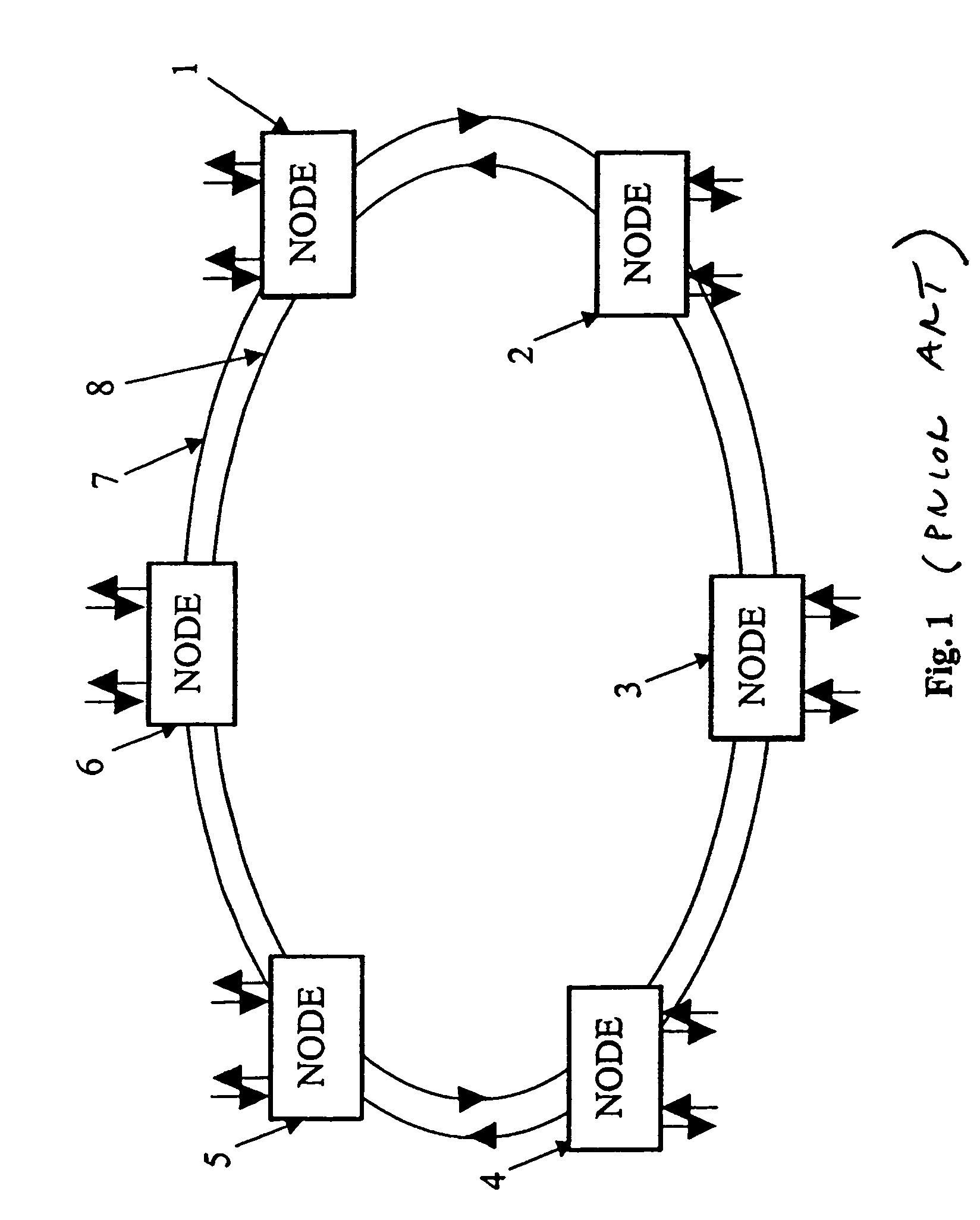
[0026]A schematic drawing of an embodiment of a WDM ring network is given in FIG. 1. Optical fibres interconnect six nodes 1, 2, 3, 4, 5, 6. Two optical fibre paths form two rings 7, 8. The nodes add and drop signals to and from these rings. The communication traffic in the two rings travels in opposite directions. The traffic pattern is meshed, i.e. each node has direct access to every other node in the ring via a dedicated wavelength channel. This is typical for a traffic pattern high up in a network hierarchy (core rings). Further down in the network hierarchy closer to the end user (access rings), the traffic pattern is typically hubbed, i.e. one central node, the hub, has a direct connection (a dedicated wavelength channel) to every other small node (called satellite node). Satellite nodes have no direct wavelength channels in between each other.

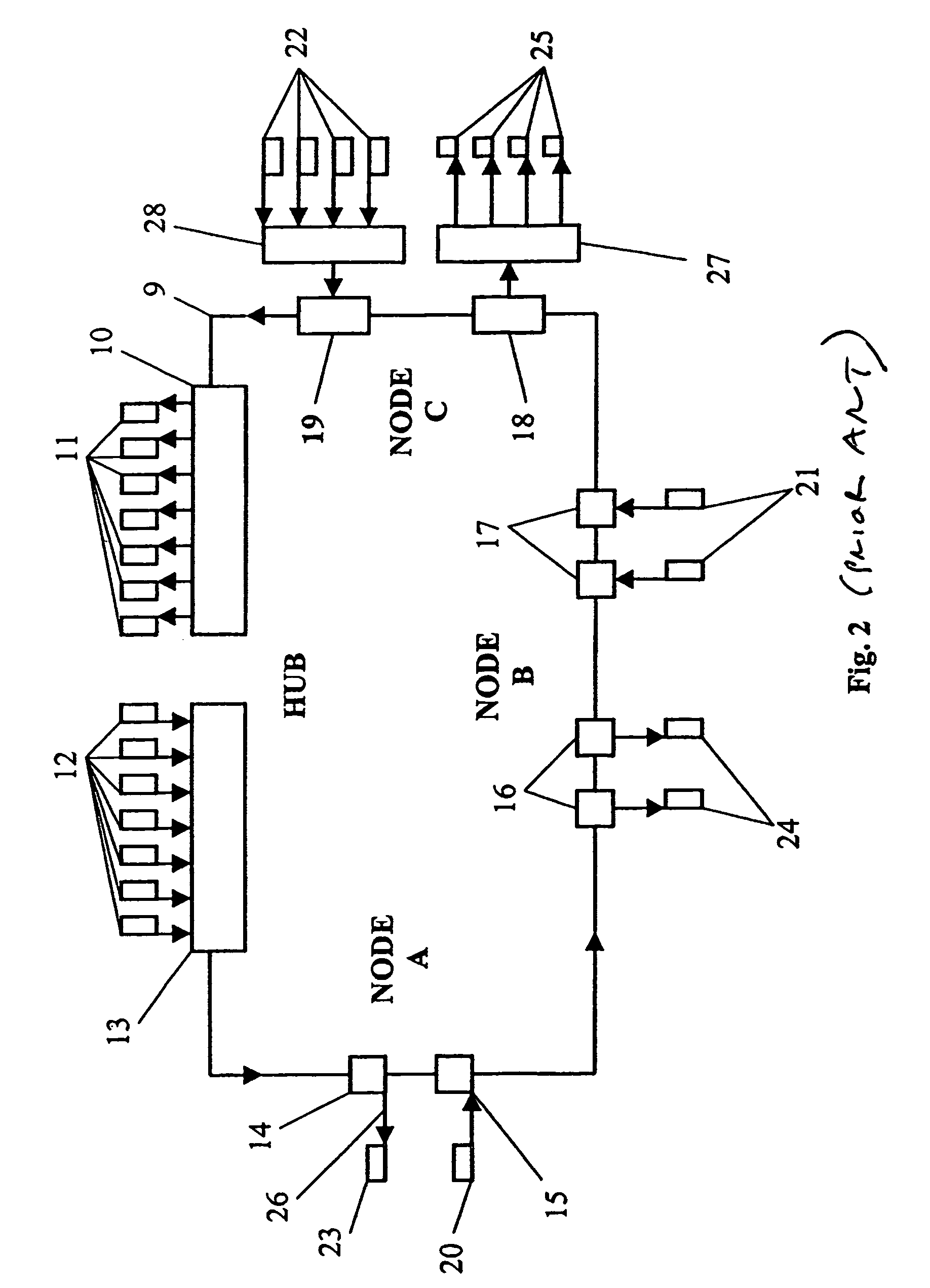
[0027]An example of a hubbed WDM ring is shown in FIG. 2. Only one fibre ring 9 is shown for clarity. Normally, there are two fibre ri...


PUM


Abstract

The present invention relates to a method using a node, a system comprising a node and a node for filtering signals in a wavelength division multiplexing (WDM) optical communications system, especially for re-configurably adding and dropping signals to and from an optical fibre path. The node comprising a drop filter, an add filter, a signal channel receiver, and a signal channel transmitter each being connected to a switch for signal channel relaying between said network, and signal channel dropping and adding from and to said network. The node provides low loss for relayed signals by allowing the drop filter to have a low crosstalk isolation, and provides high crosstalk isolation for dropped signal channels by connecting said receiver to the switch through an additional filter with high filtering characteristics for at least one predetermined signal channel of said signal.

Description

BACKGROUND OF THE INVENTION[0001]1. Technical Field[0002]The present invention pertains to a method, a system and a node for filtering signals in a wavelength division multiplexing (WDM) optical communications system, especially for re-configurably adding and dropping signals to and from an optical fiber path.[0003]2. Description of Related Art[0004]Wavelength division multiplexing (WDM) is a method for high bandwidth transmissions in optical fibre communication systems. In WDM, the optical transmission spectrum is divided into a number of separated wavelength bands, where each wavelength supports a single communication channel. Several channels can be transmitted simultaneously on the same optical fibre. WDM can be used for point-to-point communication where two nodes, one in each end of the fibre, are connected, or for multipoint-to-multipoint communication where several nodes share the transmission capacity on one fibre or one pair of fibres. In the case of multipoint-to-multipoi...

Claims


Application Information

Patent Timeline
Patent Type & Authority Patents(United States)
IPC IPC(8): G02B6/26G02B6/42H04J14/02
CPCH04J14/0206H04J14/0212H04J14/0241H04J14/0283H04J14/0213H04J14/0227
Inventor PERSSON, ULF
Owner LUMENTIS
Why Eureka
Try Eureka