Device and method for determining a temperature-dependent impedance curve along an electrical conductor

a technology of temperature-dependent impedance and measurement method, which is applied in the direction of resistance/reactance/impedence, impedence measurement, instruments, etc., can solve the problems of not being very portable, affecting the accuracy of measurement results, and increasing the line impedance in some cases, so as to reduce the determination effort for the predefined frequency spectrum

Inactive Publication Date: 2020-07-30
LEONI KABEL GMBH
View PDF0 Cites 0 Cited by
  • Summary
  • Abstract
  • Description
  • Claims
  • Application Information

AI Technical Summary

Benefits of technology

[0016]An advantage of amplifying the signal, in particular before the passage through the electrical conductor, is that signal losses due to the attenuation of the conductor in relation to the signal strength are reduced.
[0032]In one variant the electrical conductor can be enclosed in particular by a dielectric with temperature-variant properties. In particular, a dielectric constant of the dielectric enclosing the conductor can change with increasing or decreasing temperature. For example, the conductor can be a coaxial cable with a PVC dielectric. The temperature-variant properties of the dielectric can promote an impedance increase of the conductor in consequence of a local or constant heating of the conductor, so that heating of the conductor can be identified / determined more easily / simply / clearly by the device described here.

Problems solved by technology

A consequence is heating of the charging cable in sections or completely, accompanied by a significant increase in the line impedance in some cases.
If the cable is not severed but is damaged at one point, so that an impedance of the cable is increased in the region of the damage, the increased impedance causes a partial reflection of the signal.
A disadvantage of the known methods (FDR, TDR) is that the measuring devices or measuring set-ups required for these are expensive, technically complex and not very portable due to their size and their weight.
The application areas of known measuring devices are therefore limited to laboratories or extremely cost-intensive application fields in which the high costs of the measuring device recede into the background (e.g. submarine cables, oil pipelines).
For less cost-intensive application areas, for example checking shorter cables with a length of e.g. 10 m, the use of the known devices and methods makes no sense for economic reasons and is therefore uncommon.

Method used


Image

  • Device and method for determining a temperature-dependent impedance curve along an electrical conductor
  • Device and method for determining a temperature-dependent impedance curve along an electrical conductor
  • Device and method for determining a temperature-dependent impedance curve along an electrical conductor

Examples


Embodiment Construction

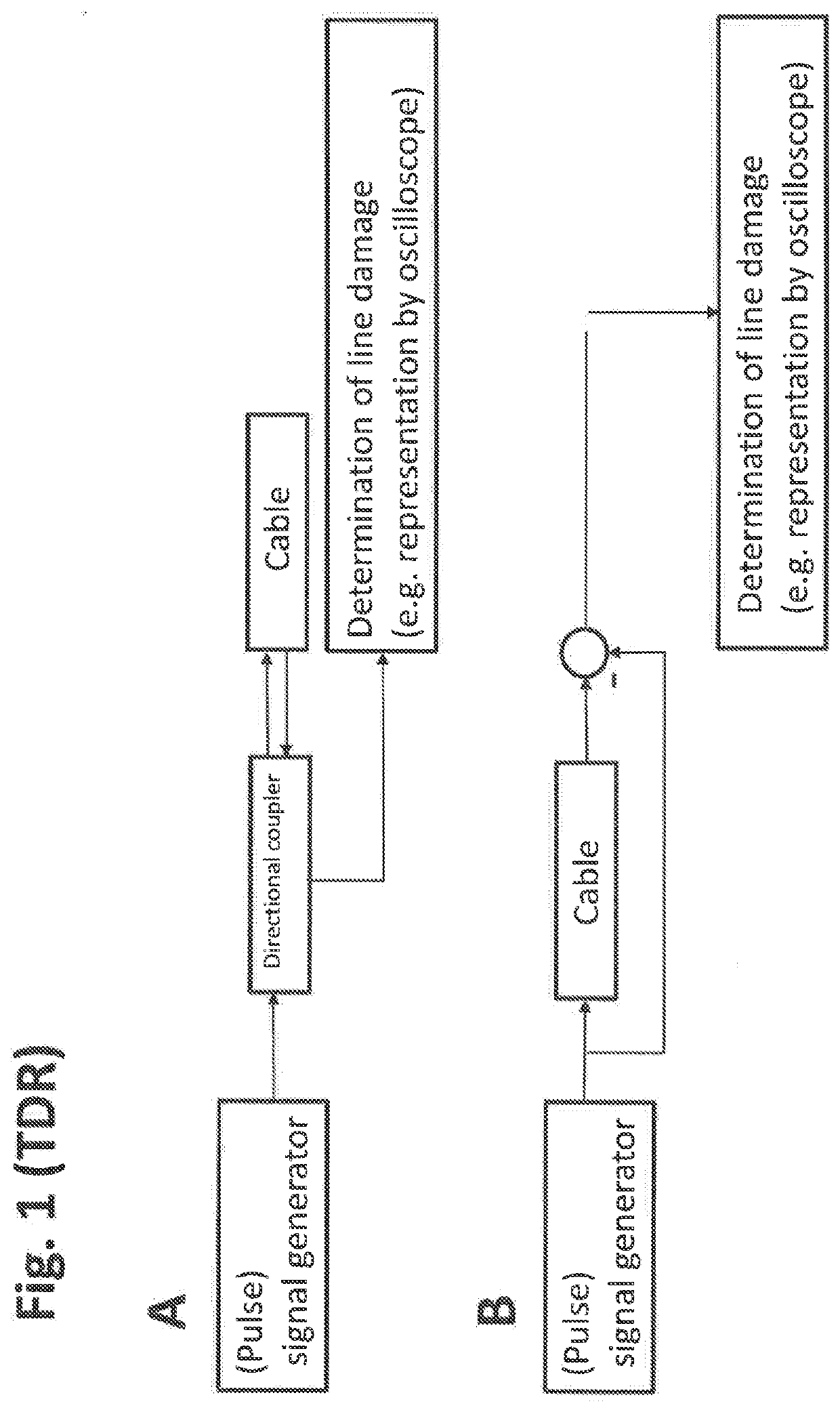
[0049]FIG. 1 shows schematically the construction of a measuring arrangement for time domain reflectrometry.

[0050]In the variant A shown in FIG. 1, a (pulse) signal is supplied via a directional coupler to a cable. The cable is connected electrically conductively to the directional coupler only at one end, while an opposite cable end is open or electrically isolated.

[0051]A (pulse) signal reflected by the cable end is led out by the directional coupler and supplied to an evaluation or representation means, for example with an oscilloscope. The cable length can be deduced by determining the propagation time of the signal.

[0052]If the cable is cut at one point, the (pulse) signal is reflected at this point. A position of the separation point can be determined by a propagation time measurement of the reflected signal.

[0053]If the cable is not cut, but is damaged at a point, so that an impedance of the line is increased at a point or in a locally delimited area, the increased impedance ...


PUM

PropertyMeasurementUnit
frequencyaaaaaaaaaa
temperatureaaaaaaaaaa
lengthaaaaaaaaaa

Abstract

The invention relates to a device for determining a temperature-dependent impedance curve along an electrical conductor, which device has a signal generator unit, which is arranged and designed to generate a multi-frequency electrical signal, which passes through an electrical conductor. The device also has a frequency spectrum sensing unit, which is arranged and designed to sense a frequency spectrum of a multi-frequency electrical signal leaving the conductor at least in a predefined frequency range. The device also has a frequency spectrum difference determination unit, which is arranged and designed to determine a frequency difference between the sensed frequency spectrum and a predefined frequency spectrum. The device also has a frequency difference conversion unit, which is designed and arranged to determine an amplitude curve of the determined frequency difference along the electrical conductor.

Description

RELATED APPLICATIONS[0001]This application filed under 35 U.S.C § 371 is a national phase application of International Application Serial Number PCT / EP2018 / 070725 filed Jul. 31, 2018, which claims the benefit of German Application No. 10 2017 213 931.5 filed Aug. 10, 2017, the entirety of which are incorporated by herein by reference.TECHNICAL FIELD[0002]The invention relates to a device and a method for determining a temperature-dependent impedance curve along an electrical conductor.BACKGROUND OF THE INVENTION[0003]Electrical conductors may get hot due to electric currents, for example, which flow through the electrical conductor. The properties of the conductors, for example an impedance of the conductors, can change due to this.[0004]In the technical field of electromobility, for example, charging cables are used to charge batteries of electric vehicles, through which cables there are flowing currents with considerable current intensity in part during a charging operation. A con...

Claims


Application Information

Patent Timeline
Patent Type & Authority Applications(United States)
IPC IPC(8): G01R27/16G01R27/04G01R23/163
CPCG01R27/16G01R27/04G01R23/163G01R31/11
Inventor INTELMAN, SERGEY
Owner LEONI KABEL GMBH
Why Eureka
Try Eureka