X-ray diffraction apparatus and method

a technology of x-ray diffraction and x-ray diffraction, which is applied in the direction of instruments, tubes with screens, image-conversion/image-amplification tubes, etc., can solve the problems of reducing the useful life of parts, creating undue downtime, and requiring requisite labor for removal and replacement of parts, and determining the remaining useful life of parts before they need to be retired

Inactive Publication Date: 2005-09-08
PROTO MANUFACTURING LTD
View PDF31 Cites 7 Cited by
  • Summary
  • Abstract
  • Description
  • Claims
  • Application Information

AI Technical Summary

Benefits of technology

[0012] In accordance with the present invention, an x-ray diffraction apparatus and method are provided in which an x-ray or goniometer head can be adjusted in different directions to allow the head to direct x-rays at a part from various positions. In this manner, measurements can be taken from a wider region of the part without requiring that the part itself be moved or that an operator move the unit, which can be relatively heavy. In one aspect, the head can be rotated about its internal axis so that it can more readily direct x-rays along curved surfaces of parts while keeping a substantially constant distance therefrom. It is preferred that the apparatus be a portable unit including adjustment mounts to allow the x-ray head to be moved in the different directions so that it can be transported for use in the field at the site at which a part is located. In this instance, the unit allows for measurements to be taken from the part while it remains in service. Accordingly, the present portable unit allows for x-ray diffraction techniques to be used on parts where it is not practical or economic to remove them from service, such as cables or wire ropes used as tension members for bridges. Moreover, the preferred portable x-ray diffraction unit herein provides an easy to interpret readout of the results of its measurements by generating a map at the part site so that, for example, any abnormalities in stress measurements taken will be highlighted in comparison to adjacent points on the map where more normal measurements are shown.
[0013] In one form of the invention, an apparatus is provided having an x-ray head adjustable in at least three mutually transverse axes for directing x-rays from different positions toward a part. The apparatus includes a frame for supporting the x-ray head. An x-axis adjustment mount of the frame is provided and which is operably connected to the head for adjusting the head in an x-axis fore and aft direction. A y-axis adjustment mount of the frame is provided and which is operably connected to the head for adjusting the head in a y-axis lateral direction. A z-axis adjustment mount of the frame is provided and which is operably connected to the head for adjusting the head in a z-axis vertical direction. Accordingly, the present x-ray diffraction apparatus is significantly improved in terms of its ability to coordinate movements of the head in three different axes of movement so that it can scan across a region of a part and direct x-rays thereat from different positions for taking measurements at a larger range of positions on the part than had been available via prior x-ray diffraction equipment. As the adjustment mounts are preferably integrated with the frame that supports the x-ray head, there is little need for operator intervention to move the part to reach the different points thereon from which measurements are desired to be taken.

Problems solved by technology

While using coupons or removing the part from service for measurement by x-ray diffraction laboratory equipment is done, neither is particularly satisfactory in that coupons require a portion of the part to be removed therefrom, and removing a part to be measured from service can create undue downtime along with the requisite labor for removal and replacement of the part back into service.
Portable x-ray diffraction equipment is known, however, some of these units suffer from great bulk making them less than ideal for use in field conditions.
When the only measurements taken are those including such localized aberrations, the determination of what the remaining useful life of the part is before it needs to be retired to avoid fatigue failure thereof can be compromised.
As is apparent, such operator intervention is time consuming and labor intensive.
In either instance, there is significant operator intervention that is required which is undesirable.
In this regard, currently there is no means available to directly and quantitatively measure the total strain and hence be able to calculate the total stress non-destructively, the dead load strain and hence the dead load stress on the following: wire rope and / or single strand and / or multi-strand cables once they are installed on a structure or component.
In addition there is no technique which can determine the strains on individual strands which may comprise a cable bundle or wire rope.
Another problem is that currently there is no means available to directly, accurately and non-destructively track the changes in wire rope and cable strain due to corrosion, creep, fatigue, overload etc.
A further problem is that currently there is no means available to directly and quantitatively and non-destructively measure the strain and hence be able to calculate the stress on the following: wire rope and or single strand and or multi-strand cables installed on an existing structure or component.
Despite the widespread use of cables, there are few tools available to inspect and characterize the stresses on cables.
This is because the accuracy of the measurement is less than ideal, the total stress in the cable is ignored and the techniques cannot characterize individual strands which may comprise a cable bundle.

Method used


Image

  • X-ray diffraction apparatus and method
  • X-ray diffraction apparatus and method
  • X-ray diffraction apparatus and method

Examples


Embodiment Construction

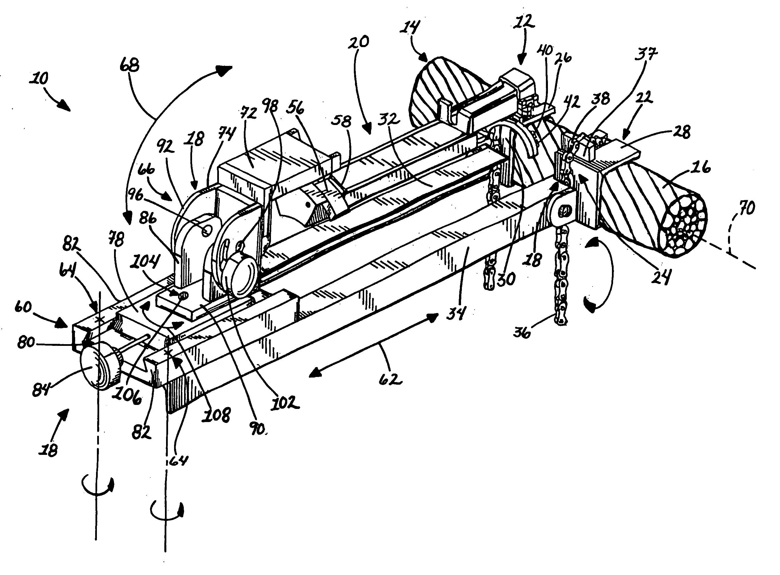
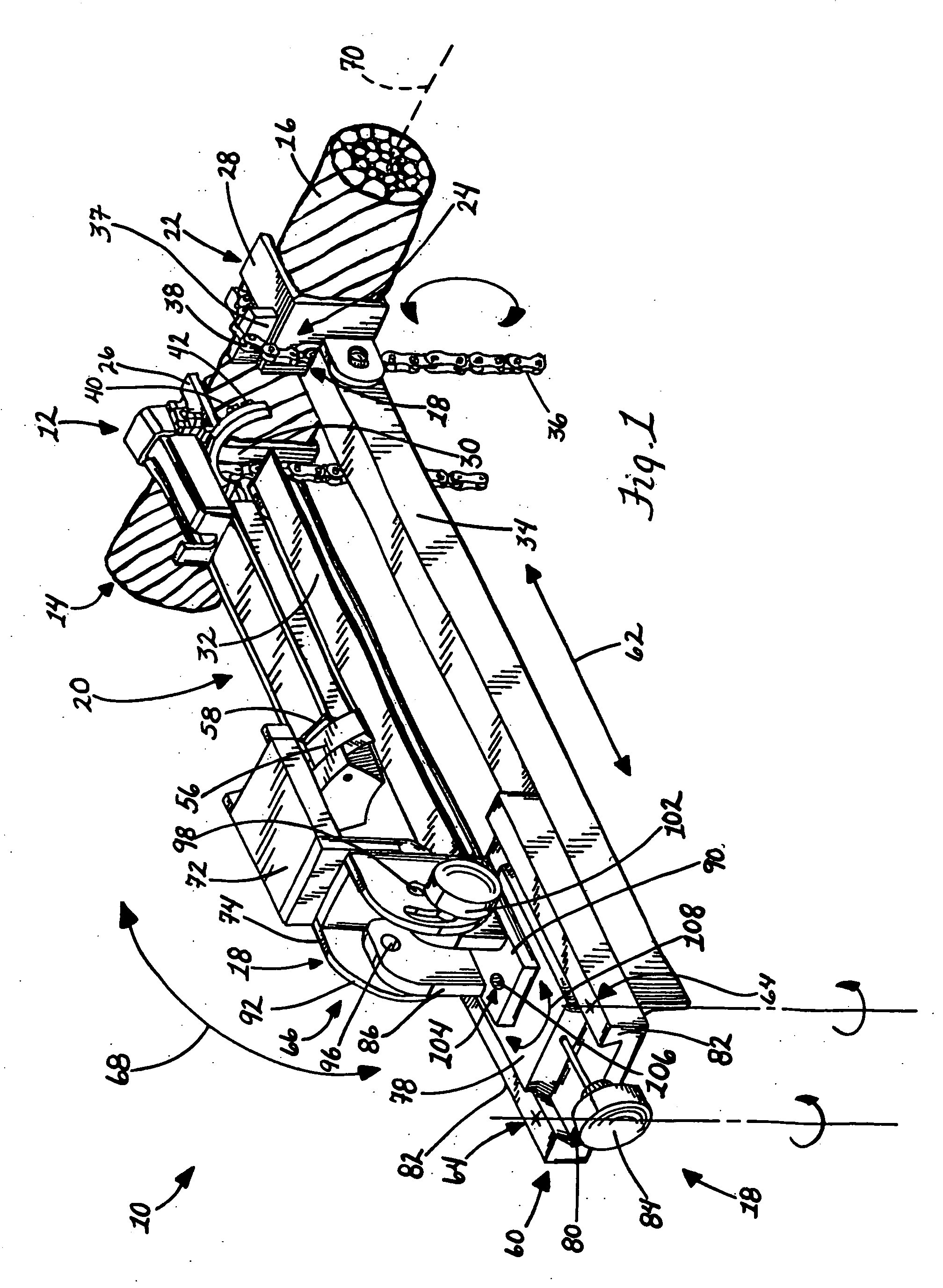
[0039] In FIG. 1, an x-ray diffraction apparatus 10 in accordance with the present invention is shown. The apparatus 10 includes an x-ray head 12 from which x-rays are directed at a part 14, such as the illustrated bridge tension member 16. The main advantage provided by the present apparatus 10 is in the ability of the x-ray head 12 to be moved in a plurality of different directions relative to the part via various adjustment mounts, generally designated 18, that are provided on frame structure 20 supporting the x-ray head 12 for its movements. In this regard, the adjustment mounts 18 afford the head 12 a range of movement so that the head 12 can direct x-rays at the part from different positions thereof and at corresponding different positions on the part 14. As discussed, this is particularly helpful where the part 14 is in service and subject to various use and environmental conditions that can cause highly specific and localized variations in the strength-related characteristic...


PUM

PropertyMeasurementUnit
movementsaaaaaaaaaa
stress mapsaaaaaaaaaa
sizesaaaaaaaaaa

Abstract

In accordance with the present invention, an x-ray diffraction apparatus and method are provided in which an x-ray or goniometer head can be adjusted in different directions to allow the head to direct x-rays at a part from various positions. In this manner, measurements can be taken from a wider region of the part without requiring that the part itself be moved or that an operator move the unit, which can be relatively heavy. In one aspect, the head can be rotated about its internal axis so that it can more readily direct x-rays along curved surfaces of parts while keeping a substantially constant distance therefrom. It is preferred that the apparatus be a portable unit including adjustment mounts to allow the x-ray head to be moved in the different directions so that it can be transported for use in the field at the site at which a part is located. In this instance, the unit allows for measurements to be taken from the part while it remains in service. Accordingly, the present portable unit allows for x-ray diffraction techniques to be used on parts where it is not practical or economic to remove them from service, such as cables or wire ropes used as tension members for bridges. Moreover, the preferred portable x-ray diffraction unit herein provides an easy to interpret readout of the results of its measurements by generating a map at the part site so that, for example, any abnormalities in stress measurements taken will be highlighted in comparison to adjacent points on the map where more normal measurements are shown.

Description

CROSS REFERENCE TO RELATED APPLICATION [0001] This is a continuation of prior application Ser. No. 10 / 781,417, filed Feb. 18, 2004, which is a divisional application from prior application Ser. No. 09 / 539,346, filed Mar. 31, 2000, now issued as U.S. Pat. No. 6,721,393 B1, which is hereby incorporated herein by reference in its entirety.FIELD OF THE INVENTION [0002] The invention relates to an apparatus and method for measuring strength related characteristics of a part using x-ray diffraction techniques and, more particularly, to an apparatus and method for measuring the strength related characteristics at a variety positions on the part. BACKGROUND OF THE INVENTION [0003] The use of x-ray diffraction techniques for measuring residual stresses in crystalline substances such as metal or ceramic materials is well-known. The general idea with the use of x-ray diffraction is to subject the material to the radiation of x-rays with the resulting sensed x-ray diffraction peak interpreted t...

Claims


Application Information

Patent Timeline
Patent Type & Authority Applications(United States)
IPC IPC(8): G01N23/20
CPCG01N23/20016G01N23/20
Inventor BRAUSS, MICHAEL
Owner PROTO MANUFACTURING LTD
Why Eureka
Try Eureka