Large crossbar switch implemented in FPGA

a crossbar switch and programmable gate array technology, applied in the field of field programmable gate arrays (fpgas), can solve the problem of impracticality of using all these inputs

Inactive Publication Date: 2006-06-06
XILINX INC
View PDF5 Cites 50 Cited by
  • Summary
  • Abstract
  • Description
  • Claims
  • Application Information

AI Technical Summary

Benefits of technology

[0017]In communications use, FPGAs implementing crossbar switches are reconfigured to change which input is connected to which output, but most of the configuration is retained. In one embodiment, to change the connectivity, the lookup tables and routing are not reconfigured, and only the IMUXs are reconfigured. A table of configuration values may be stored in a computer that configures the FPGA, one set of bits to be turned on for each input-to-output connection, and used to set up the configuration bitstream for a partial reconfiguration due to changing connectivity of the crossbar switch. An algorithm for generating the bits may also be used. By taking advantage of the regularity and the fact that the CLBs are identical, the algorithm would simply generate bitstream instructions based on the desired location with a CLB.

Problems solved by technology

Making use of all these inputs may be impractical due to limitations in routing available in the Virtex-II FPGA.

Method used


Image

  • Large crossbar switch implemented in FPGA
  • Large crossbar switch implemented in FPGA
  • Large crossbar switch implemented in FPGA

Examples


Embodiment Construction

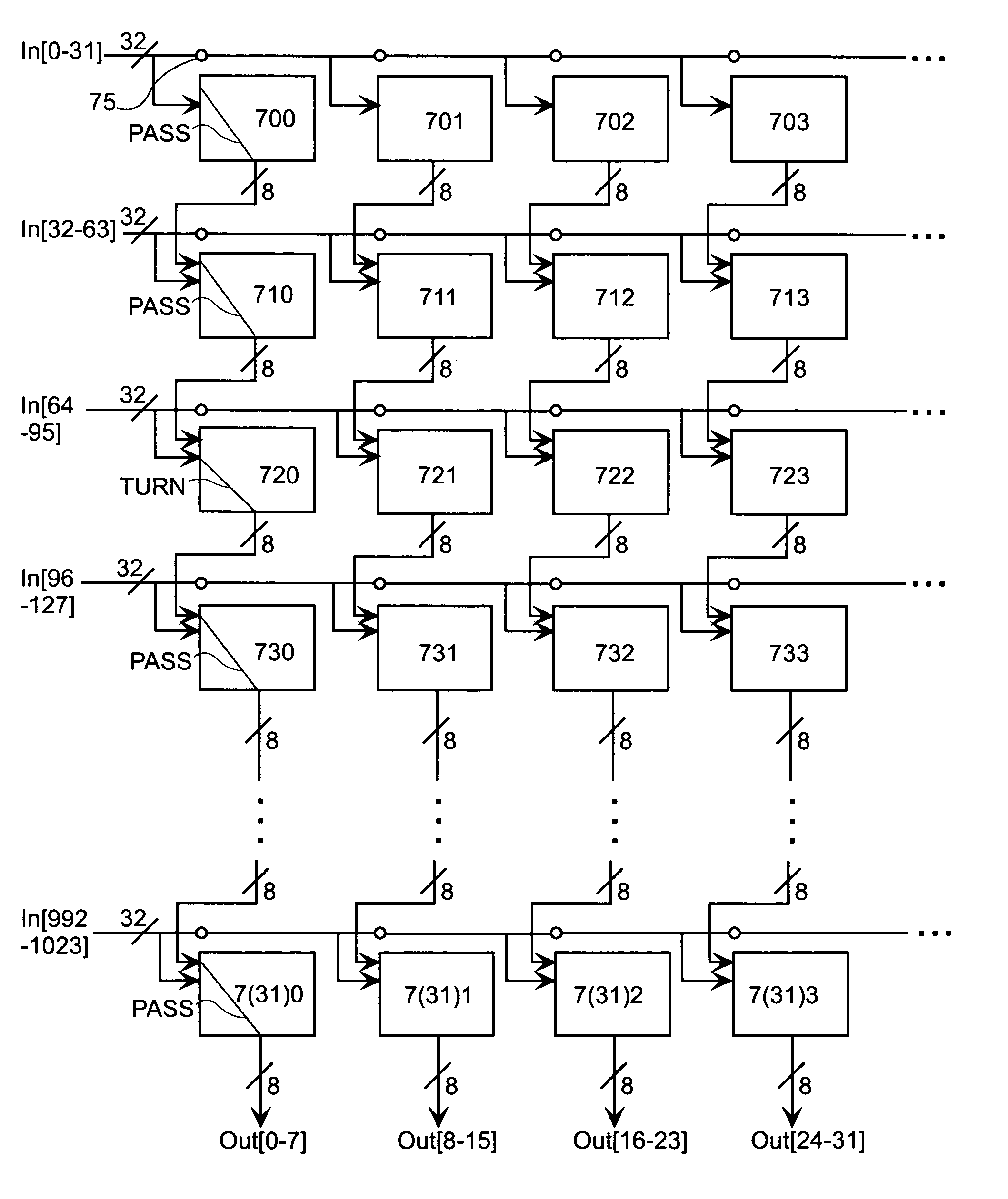
[0032]FIG. 4 shows one embodiment of the crossbar switch of the present invention. Input lines In0 through In1023 come from the left and are connectable through CLBs 700 through 7(31)3 and more not shown to output lines Out0 through Out31 and more not shown. In FIG. 4, horizontal interconnect lines in the FPGA are connected by programmable interconnection points (PIPs) such as PIP 75 (represented here by small circles) to form long horizontal routing lines. Each CLB receives signals on 32 input lines from the left and provides signals on 8 output lines extending downward. For example, CLBs 710, 711, 712, and 713 (and more not shown) receive input signals on lines In32 through In63. These four CLBs also receive input signals from CLBs 700, 701, 702, and 703, respectively. Thus, in FIG. 4, each CLB receives 40 input signals, 32 from the left, and 8 from above. Each CLB provides 8 output signals on lines connected to the CLB below.

[0033]Within each CLB, multiplexers are programmed by m...


PUM


Abstract

A method for using an FPGA to implement a crossbar switch is described. Rather than using signals routed through the general FPGA routing resources to control connectivity of the crossbar switch, the input signals only carry crossbar switch data, and the connectivity is controlled by FPGA configuration data. The crossbar switch is implemented in two parts: a template of basic and constant routing to carry input signals through the switch array in one dimension and output signals from the array in another dimension, and a connectivity part controlled by a connectivity table or algorithm to generate partial reconfiguration bitstreams that determine which of the input signals is to be connected to which of the output signals.

Description

[0001]This application is a con. of Ser. No. 10 / 164,508 files on Jun. 5, 2002 now U.S. Pat. No. 6,759,869.FIELD OF THE INVENTION[0002]The present invention relates to uses made of field programmable gate arrays (FPGAs), in particular to use of an FPGA to route information from selected input points to selected output points.BACKGROUND[0003]FPGAs are frequently used for telecommunication. An essential aspect of telecommunication is the ability to route information from any source to any desired destination. A crossbar switch accomplishes this purpose.[0004]FIG. 1 shows a simple crossbar switch. Eight input lines IN0 through IN7 carry input signals and eight output lines OUT0 through OUT7 provide output signals. An array of connectors can be selectively turned on to provide any of the input signals as an output signal. For example, turning on connector C0,0 connects input line IN0 to output line OUT0. Turning on connector C0,7 connects input line IN0 to output line OUT7. It is importa...

Claims


Application Information

Patent Timeline
Patent Type & Authority Patents(United States)
IPC IPC(8): H03K19/177H04Q3/00H04Q3/52
CPCH03K19/17736H03K19/17748H03K19/17752H04Q3/0004H04Q3/521H03K19/17756H04Q2213/13076
Inventor YOUNG, STEVEN P.ALFKE, PETER H.BAUER, TREVOR J.FEWER, COLM P.
Owner XILINX INC
Why Eureka
Try Eureka