

Multi-band flat antenna
a flat antenna and multi-band technology, applied in the direction of resonant antennas, helical antennas, non-resonant long antennas, etc., can solve the problems of interference problems between radiators, the size of these antennae still cannot be effectively miniaturized to meet the desired requirement, etc., and achieve the effect of minimizing the antenna siz
- Summary
- Abstract
- Description
- Claims
- Application Information
AI Technical Summary
Benefits of technology
Problems solved by technology
Method used
Image

Examples
first embodiment
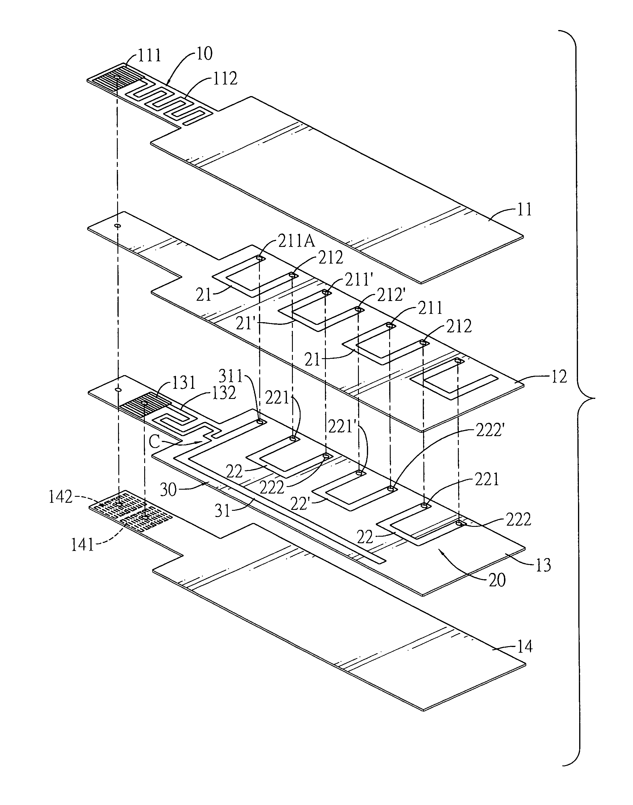
[0041]With reference to FIG. 6, a multi-band flat antenna of the present invention has a construction that is composed of plural substrates (11–14) constituted of ceramic, glass fiber, Teflon™ or other dielectric materials. A first radiation unit (20) to be operated in a first frequency band, a second radiation unit (30) to be operated in a second frequency band, and a third radiation unit (10) to be operated in a third frequency band are formed on these substrates (11–15).
[0042]The top substrate (11) serves as a base for carrying the third radiation unit (10) thereon. The bottom substrate (14) is an isolating layer, wherein two external feeding ports (141)(142) are formed on a protrusion extending from one edge of the bottom substrate (14). The first external feeding port (141) serves as a signal feeding terminal for the first and second radiation units (20)(30). The second external feeding port (142) functions as a signal feeding terminal for the third radiation unit (10).
[0043]Th...
third embodiment
[0059]With reference to FIG. 11, the multi-band flat antenna is also similar to two previous embodiments. The changed portion is that straight line circuits (21), inverted U-shaped circuits (22) and U-shaped circuits (23) of the first radiation unit (20) are sequentially formed on a second, third and fourth substrates (12–14), where these circuits (21–23) are also interconnected to each other to configure the three-dimensional structure by the PTH interconnecting process.
[0060]Two distal ends (221)(222) of an inverted U-shaped circuit (22) are respectively connected to distal ends (211) of two adjacent straight circuits (21). The other distal ends (212) of the straight circuits (21) are connected to the ends (232)(231) of the U-shaped circuits (23). When all the substrates (11–15) are compressed, all the circuits (21–23) are interconnected by PTH processes. Consequently, the second end (232) of the first U-shaped circuit (23) at the left-most side of the substrate (14) can connect t...
fourth embodiment
[0065]For example, with reference to FIG. 12, the flat antenna is substantially the same as the foregoing embodiments. The first radiation unit (20) is also created by the U-shaped circuits (23), the straight circuits (21) and the inverted U-shaped circuits (22) that are sequentially formed on the second to the fourth substrates (12–14) and interconnected in a meandering configuration.
[0066]The second radiation unit (30) forms an L-shaped trace on the fourth substrate (14). An internal feeding port (144) formed on the same substrate (14) is connected to the second radiation unit (30) through a signal transmission circuit (145). The internal feeding port (144) is further connected to a first external feeding port (151) on the bottom substrate (15) by PTH processes.
[0067]The third radiation unit (10) formed on the second substrate (12) has one end connected to an internal feeding port (121), and the other end is kept in the open circuit status. The internal feeding port (121) is conne...
PUM
 Abstract
Description
Claims
Application Information