Audio synchronization pulse for multi-camera capture systems

a multi-camera capture and audio synchronization technology, applied in the field of multi-camera capture systems, can solve the problems of synchronizing the video streams from the multiple, requiring intensive processing of captured video by a camera with a hemispherical lens, and reducing the resolution of two-camera systems

Inactive Publication Date: 2006-06-06
B H IMAGE CO
View PDF8 Cites 37 Cited by
  • Summary
  • Abstract
  • Description
  • Claims
  • Application Information

AI Technical Summary

Benefits of technology

[0018]The present invention will be more fully understood in view of the following description and drawings.

Problems solved by technology

However, the images captured by a camera with a hemispherical lens require intensive processing to remove the distortions caused by the hemispherical lens.
Furthermore, two-cameras systems provide less resolution than systems having more than two cameras.
A major problem with multi-camera capture systems is synchronization of the video streams from the multiple cameras.
However, generally time code systems are only available on large expensive multi-camera capture systems, which are not suited for many applications.

Method used


Image

  • Audio synchronization pulse for multi-camera capture systems
  • Audio synchronization pulse for multi-camera capture systems
  • Audio synchronization pulse for multi-camera capture systems

Examples


Embodiment Construction

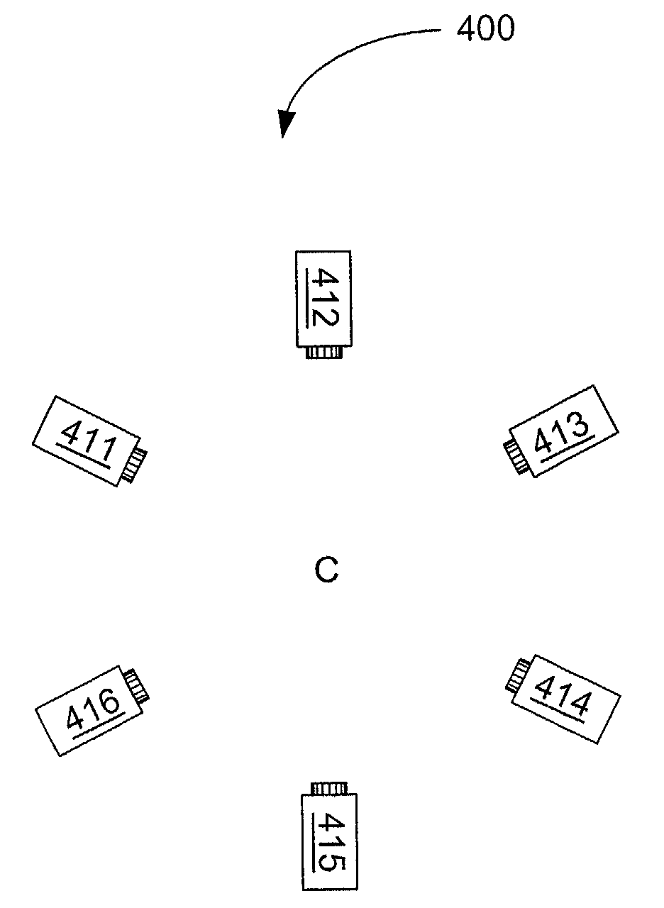
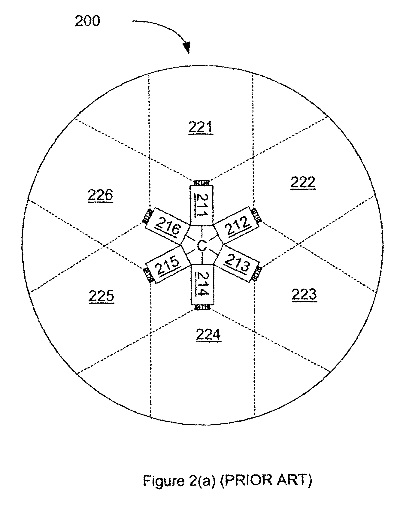
[0029]FIG. 5 shows a block diagram of a multi-camera capture system 500 with audio synchronization marker 510 in accordance with one embodiment of the present invention. Multi-camera capture system 500 includes N cameras, where N is a positive integer. Specifically, multi-camera capture system 500 includes cameras 520_1, 520_2, 520_3, 520_N. FIG. 5 only illustrates the connection between audio synchronization marker 510 and cameras 520_1 to 520_N. The actual physical arrangement of cameras 520_1 to 520_N can vary widely. For example, cameras 520_1 to 520_N may be arranged as an outward facing camera system, a pyramidal mirror camera system, an inward-facing camera system, or any other arrangement.

[0030]Audio synchronization marker 510 is configured to generate synchronizing audio signals for cameras 520_1 to 520_N. Specifically, audio synchronization marker 520 generates audio signals AS_1, AS_2, AS_3, . . . AS_N, which are provided to cameras 520_1, 520_2, 520_3, . . . 520_N, respe...


PUM


Abstract

A multi-camera capture system includes an audio synchronization marker to provide synchronization marks with the video streams captured by the multi-camera capture system. In one embodiment of the present invention, the audio synchronization marker generate a plurality of substantially similar synchronizing audio signals. Each camera of the multi-camera capture system records a synchronizing audio signal with the video stream captured by the camera. The synchronizing audio signals contain synchronization marks which are used to synchronize the video streams of the cameras.

Description

FIELD OF THE INVENTION[0001]The present invention relates to multi-camera capture systems. More specifically, the present invention relates to synchronizing the video streams captured by the cameras of a multi-camera capture systems.BACKGROUND OF THE INVENTION[0002]As the processing power of microprocessors and the quality of graphics systems have increased, advanced imaging functions such as environment mapping have become feasible on personal computer systems. Environment mapping systems use computer graphics to display the surroundings or environment of a theoretical viewer. Ideally, a user of the environment mapping system can view the environment at any angle or elevation. FIG. 1(A) illustrates the construct used in conventional environment mapping systems. A viewer 105 is centered at the origin of a three dimensional space having x, y, and z coordinates. The environment of viewer 105 (i.e., what the viewer can see) is ideally represented by a sphere 110, which surrounds viewer...

Claims


Application Information

Patent Timeline
Patent Type & Authority Patents(United States)
IPC IPC(8): H04N7/12H04N11/02
CPCH04N5/247H04N23/90
Inventor LEE, PHILIP H.
Owner B H IMAGE CO
Why Eureka
Try Eureka