Disk drive including surface coated disk clamp screws with reduced coefficient of friction for mitigating disk clamp movement

Inactive Publication Date: 2006-06-06
WESTERN DIGITAL TECH INC
View PDF11 Cites 55 Cited by
  • Summary
  • Abstract
  • Description
  • Claims
  • Application Information

AI Technical Summary

Benefits of technology

[0012]An aspect of the invention can be regarded as a disk drive that includes a disk drive base, a rotatable disk including a disk surface, and a spindle motor rotatably coupled to the disk drive base for rotating the disk about an axis of rotation. The spindle motor includes a spindle motor hub including a clamping surface with a plurality of threaded disk clamp holes. The disk drive further includes a disk clamp disposed upon the disk surface about the spindle motor hub. The disk clamp includes a screw head interface surface and a plurality of screw openings formed through the disk clamp. The disk drive further includes a plurality of disk clamp screws. The screws each includes a shaft sized and configured to respectively engage the threaded disk clamp holes respectively through the screw openings. The screws each further includes a screw head having a screw head clamping surface disposed against the screw head interface surface. The screws each further include a surface coating disposed upon the screw head clamping surface. The surface coating has a static coefficient of friction less than a static coefficient of friction of the screw head for mitigating relative movement between the disk clamp and the axis of rotation of the spindle motor. According to various embodiments of the present invention, the surface coating may include a metallic material, such as nickel. The surface coating may further be polytetrafluoroethylene. The surface coating may further include a plastic material. The

Problems solved by technology

Such interaction results in forces applied to the spindle motor hub that tend to rotate the spindle motor hub and the attached disks.
The greater the magnitude of the imbalance, the greater the degradation of the disk drive performance, not only in terms of read/write errors, but also seek times. A significant amount of imbalance may even result in damage or excessive wear to various

Method used


Image

  • Disk drive including surface coated disk clamp screws with reduced coefficient of friction for mitigating disk clamp movement
  • Disk drive including surface coated disk clamp screws with reduced coefficient of friction for mitigating disk clamp movement
  • Disk drive including surface coated disk clamp screws with reduced coefficient of friction for mitigating disk clamp movement

Examples


Embodiment Construction

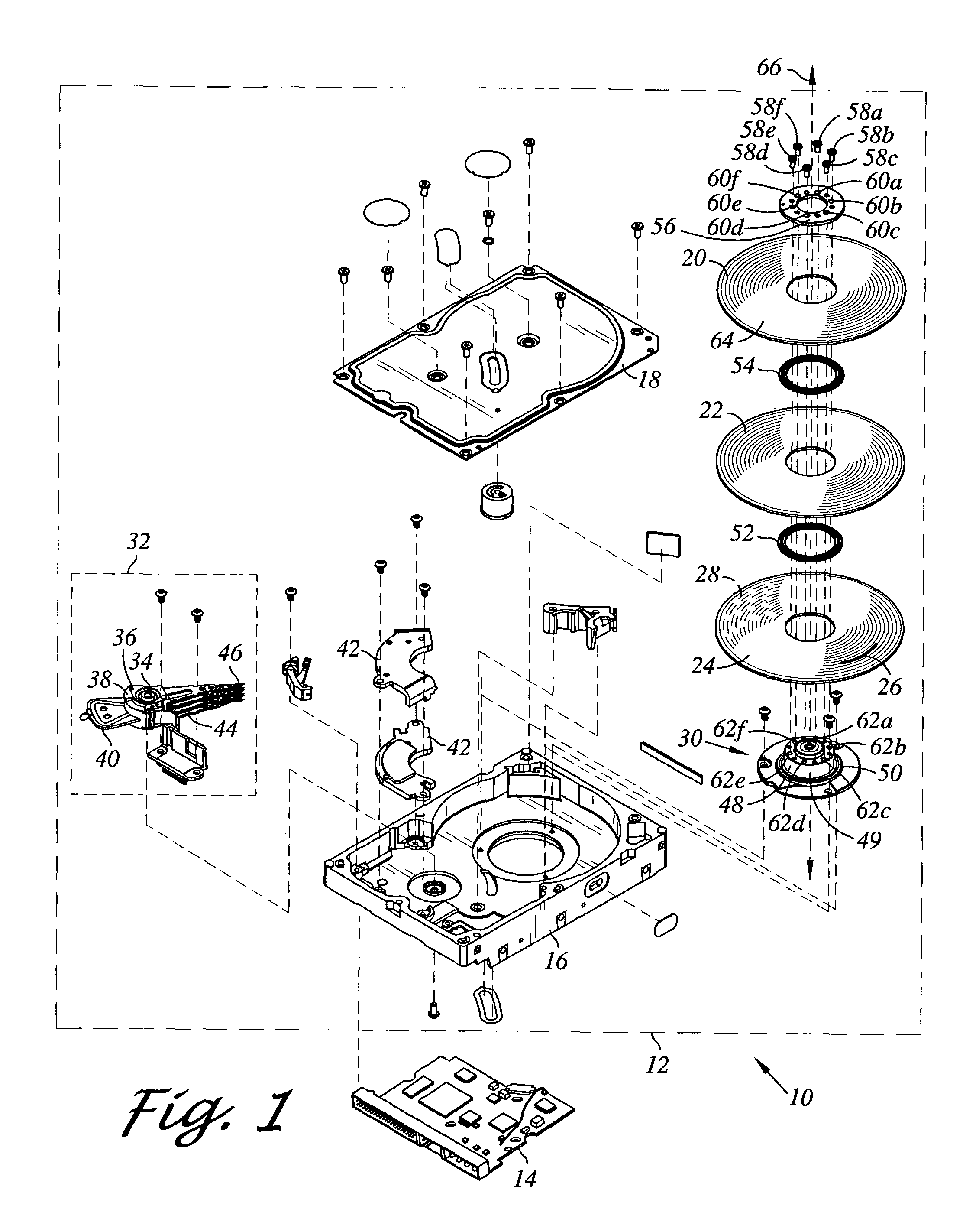
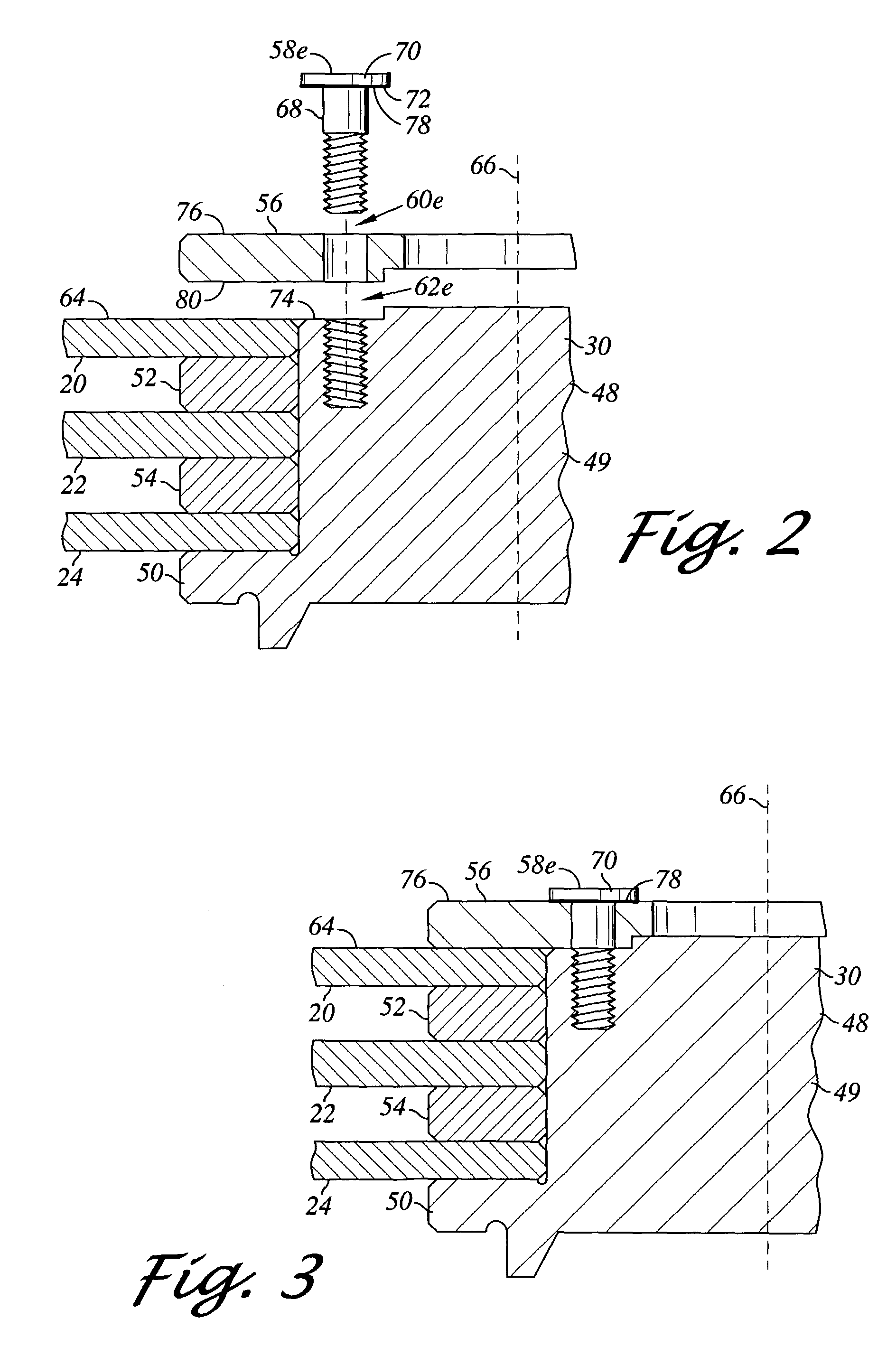
[0018]Referring now to the drawings wherein the showings are for purposes of illustrating preferred embodiments of the present invention only, and not for purposes of limiting the same, FIGS. 1–4 illustrate a disk drive and a method of mitigating disk shift during fabrication of a disk drive in accordance with the aspects of the present invention.

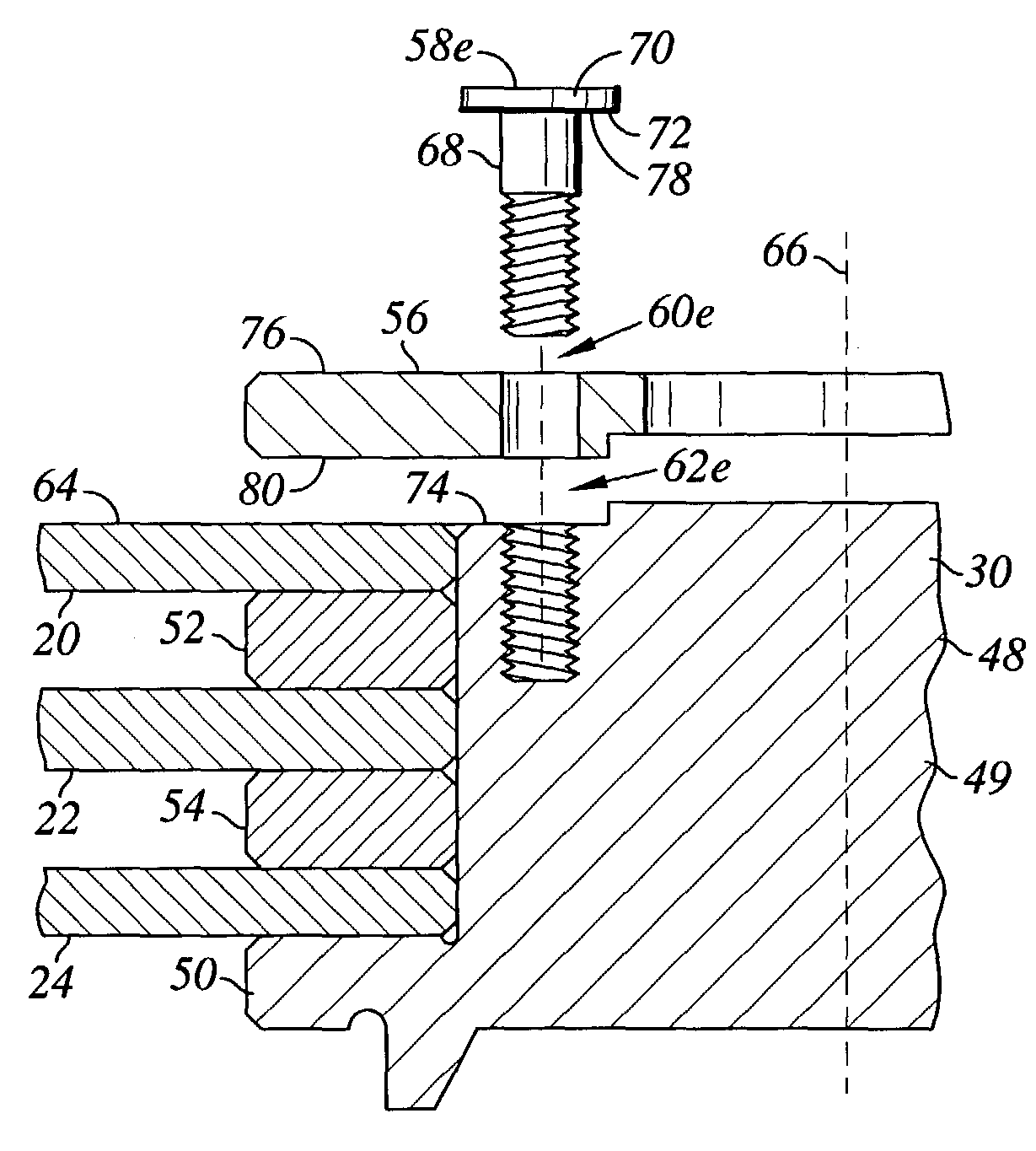
[0019]Referring now to FIG. 1 there is depicted an exploded perspective view of a disk drive 10 constructed in accordance with an aspect of the present invention. In the embodiment shown, the disk drive 10 includes a head disk assembly (HDA) 12 and a printed circuit board assembly (PCBA) 14. The head disk assembly 12 includes a disk drive base 16 and a cover 18 that collectively house magnetic disks 20, 22, 24. Each magnetic disk 20, 22, 24 contains a plurality of tracks for storing data. The magnetic disks 20, 22, 24 may be two-sided, and thus for example, the magnetic disk 24 is shown having a track 26 on an upper facing side and a track ...


PUM


Abstract

An aspect of the invention can be regarded as a disk drive that includes a disk drive base, a disk including disk surface, and a spindle motor including a spindle motor hub including a clamping surface with disk clamp holes. The disk drive includes a disk clamp disposed upon the disk surface. The disk clamp includes a screw head interface surface and screw openings. The disk drive includes disk clamp screws each including a shaft sized and configured to respectively engage the threaded disk clamp holes respectively through the screw openings. The screws each further include a screw head having a screw head clamping surface disposed against the screw head interface surface. The screws each further include a surface coating disposed upon the screw head clamping surface. The surface coating has a static coefficient of friction less than a static coefficient of friction of the screw head.

Description

BACKGROUND OF THE INVENTION[0001]1. Cross-Reference to Related Applications[0002]Not applicable.[0003]2. Field of the Invention[0004]The present invention relates generally to disk drives, and in particular to a disk drive including surface coated disk clamp screws with reduced coefficient of friction for mitigation disk clamp movement.[0005]3. Description of the Prior Art[0006]The typical hard disk drive includes a head disk assembly (HDA) and a printed circuit board assembly (PCBA) attached to a disk drive base of the HDA. The head disk assembly includes the disk drive base, a cover, at least one magnetic disk, a spindle motor for rotating the disk, and a head stack assembly (HSA).[0007]The head stack assembly has an actuator assembly having at least one head or slider, typically several, for reading and writing data to and from the disk. The printed circuit board assembly includes a servo control system in the form of a disk controller for generating servo control signals. The he...

Claims


Application Information

Patent Timeline
IPC IPC(8): G11B17/02
CPCG11B25/043G11B17/038
Inventor BUTLER, WALTER W.HUANG, YAO-HSINLLOYD, JR., ROBERT E.
Owner WESTERN DIGITAL TECH INC
Why Eureka
Try Eureka