Brush member and transfer device and image forming apparatus using the same

Inactive Publication Date: 2007-01-18
RICOH KK
View PDF21 Cites 22 Cited by
  • Summary
  • Abstract
  • Description
  • Claims
  • Application Information

AI Technical Summary

Benefits of technology

[0007] The present invention is proposed to cope with the aforementioned problems, and it is an obje

Problems solved by technology

This tends to cause transfer

Method used


Image

  • Brush member and transfer device and image forming apparatus using the same
  • Brush member and transfer device and image forming apparatus using the same
  • Brush member and transfer device and image forming apparatus using the same

Examples


first embodiment

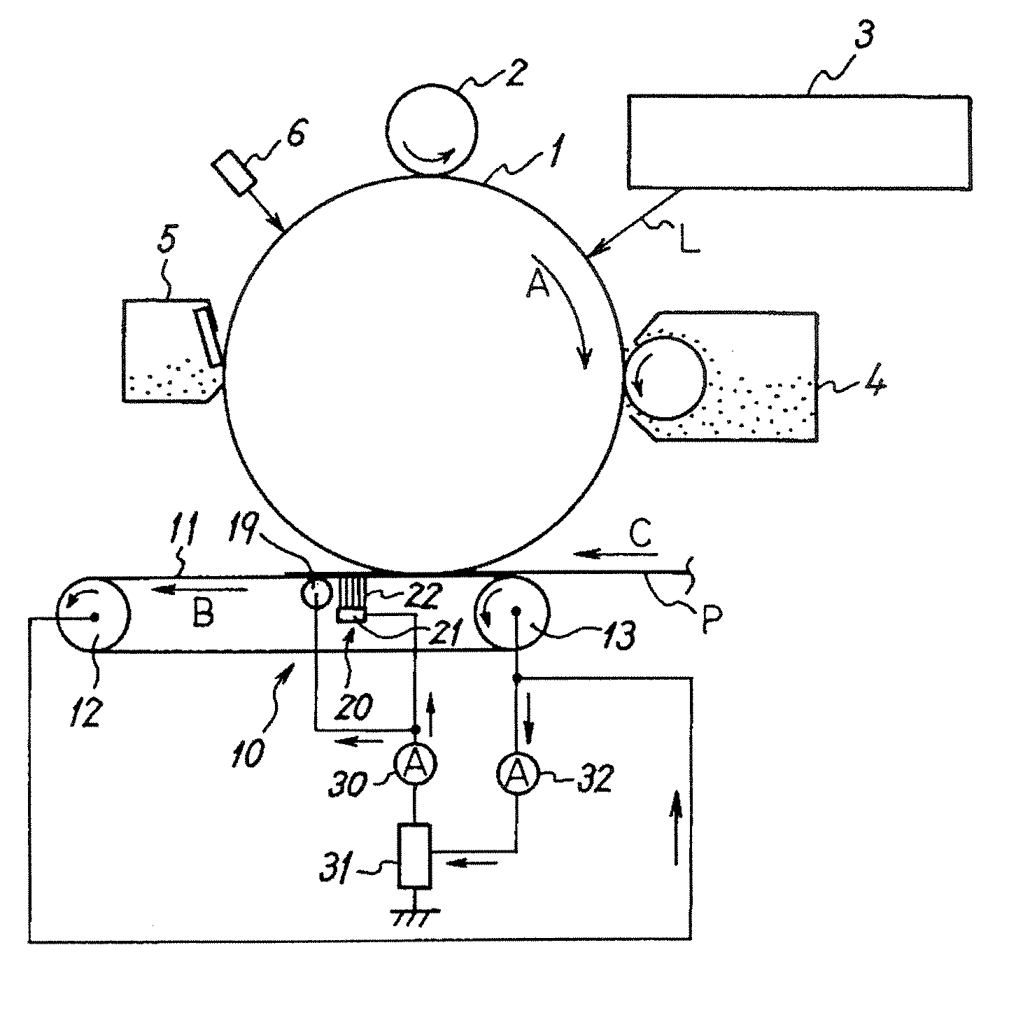
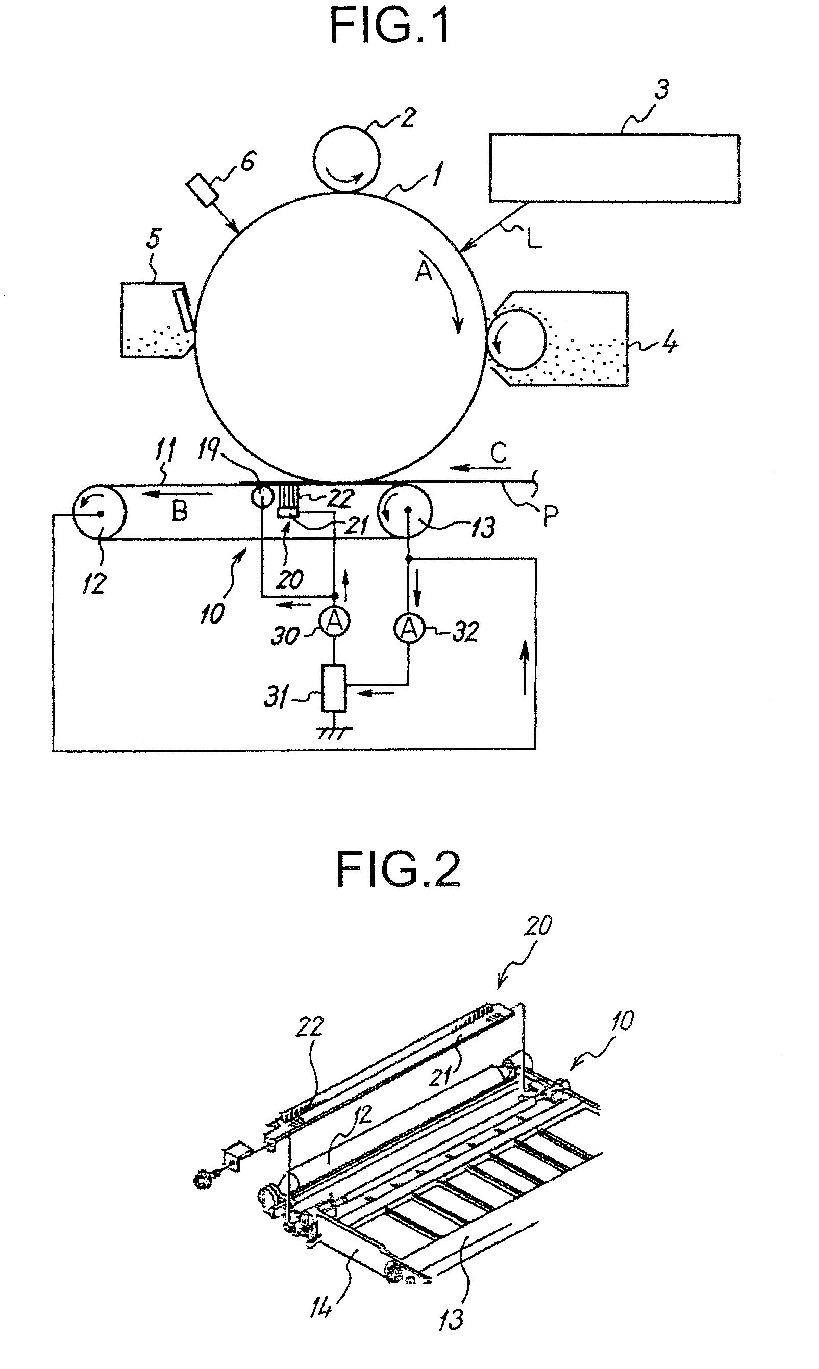
[0024]FIG. 1 is a schematic of a printer according to the present invention. In the figure, a charging roller 2, an optical writing unit 3, a developing device 4 serving as a developing unit, a transfer device 10, a drum cleaning device 5, an electricity removing lamp 6, and the like are disposed around a drum-like photosensitive member 1 serving as a latent image bearing member.

[0025] The photosensitive member 1 is driven to rotate in a clockwise direction in the figure (a direction of an arrow A in the figure) by a not-shown driving unit. The photosensitive member 1 is uniformly charged to a minus polarity in the dark by the charging roller 2 to which a charging bias is applied by a not-shown power supply. A surface potential of the photosensitive member 1 after the uniform charging is, for example, −800 volts. On the surface of the photosensitive member 1 in such a potential state, an electrostatic latent image corresponding to an image signal is formed by optical scanning by an ...

second embodiment

[0047] As shown in Table 2, it is seen that the transfer brushes 20 of nylon had small maximum bristle inclination amounts compared with that of nylon. Although not shown in Table 2, in both the two kinds of the transfer brushes 20 of nylon in Table 2, shaving of the rear surface of the paper conveyor belt 11 and transfer blurring did not occur even if the test image was printed on 100,000 pieces of transfer paper. On the other hand, in the transfer brush 20 of rayon, shaving of the rear surface of the paper conveyor belt 11 and transfer blurring occurred while the test image was printed on 100,000 pieces of transfer paper. Consequently, it was found that shaving of the rear surface of the paper conveyor belt 11 due to rubbing against the transfer brush 20 and transfer blurring due to accumulation of shavings on the brush tip could be controlled by using, as the transfer brush 20, a transfer brush with a maximum bristle inclination amount equal to or smaller than the maximum bristle...

third embodiment

As shown in Table 3, whereas maximum bristle inclination return amounts in the transfer brushes 20 of nylon were 0.30, a maximum bristle inclination return amount in the transfer brush 20 of rayon was 0.40. Consequently, it is seen that bristle inclination does not easily return to the original state in the transfer brushes 20 of nylon compared with that of rayon. Although not shown in Table 3, as described above, whereas shaving of the rear surface of the paper conveyor belt 11 and transfer blurring did not occur in both the two kinds of transfer brushes 20 of nylon, shaving of the rear surface of the paper conveyor belt 11 and transfer blurring occurred in the transfer brush 20 of rayon. Consequently, it was found that shaving of the rear surface of the paper conveyor belt 11 due to rubbing against the transfer brush 20 and transfer blurring due to accumulation of shavings on the brush tip could be controlled by using, as the transfer brush 20, a transfer brush with a maximum bris...


PUM


Abstract

In an image forming apparatus, a transfer brush with length of raised bristles on the surface of a metal holder equal to or smaller than 5.8 millimeters is used. Alternatively, a transfer brush with a maximum bristle inclination amount of raised bristles in a brush unit including a plurality of bristles equal to or smaller than 0.53 millimeter or a transfer brush with a maximum bristle inclination return amount of raised bristles in the brush unit equal to or smaller than 0.30 millimeter is used. An amount of biting into a paper conveyor belt in the brush unit is set to a value equal to or smaller than 2.5 millimeters. A paper conveyor belt with hardness of the rear side equal to or lower than 78 Hs is used. Alternatively, a paper conveyor belt with a coefficient of static friction on the rear surface equal to or lower than 0.75 is used.

Description

CROSS-REFERENCE TO RELATED APPLICATIONS [0001] The present document incorporates by reference the entire contents of Japanese priority document, 2005-207197 filed in Japan on Jul. 15, 2005. BACKGROUND OF THE INVENTION [0002] 1. Field of the Invention [0003] The present invention relates to a brush member used in a transfer device that transfers, while supplying a transfer bias to a rear surface of a moving belt member using the brush member, a visible image on the surface of a latent image bearing member onto a front surface of the belt member or a transfer material held on the front surface. The present invention also relates to transfer devices and image forming apparatuses like a copying machine, a facsimile apparatus, and a printer that use such a brush member. [0004] 2. Description of the Related Art [0005] Conventionally, in the image forming apparatuses of this type, in general, a transfer brush that has a predetermined electric resistance in a conductive brush unit including...

Claims


Application Information

Patent Timeline
IPC IPC(8): G03G15/16
CPCG03G2215/1642G03G15/1685
Inventor ISHII, HIROKAZU
Owner RICOH KK
Why Eureka
Try Eureka