Image forming apparatus, image forming method and process cartridge

a technology process cartridge, which is applied in the direction of electrographic process apparatus, instruments, optics, etc., can solve the problems of inconvenient cleaning system of blades, increase in power consumption of image forming apparatus, shortening of life, etc., and achieves long durability and good cleaning performance.

Inactive Publication Date: 2007-01-25
RICOH KK
View PDF15 Cites 22 Cited by
  • Summary
  • Abstract
  • Description
  • Claims
  • Application Information

AI Technical Summary

Benefits of technology

[0020] Because of these reasons, the present inventor recognizes that a need exists for an image forming apparatus having a long durability and maintaining good cleaning performanc

Problems solved by technology

Therefore, a blade cleaning system is not suitable when such a polymerized toner is used.
However, the toner is excessively pressed against the surface of an image bearing member, which leads to a side-effect, such as the occurrence of filming on the image bearing member.
Furthermore, abrasion of the image bearing member and the blade edge is easily accelerated, resulting in shortening of life thereof.
Furthermore, this invites the increase in the rotation torque of the image bearing member, which leads to an increase in the power consumption of the image forming apparatus.
In addition, when the contact pressure of a blade is not suitable, filming occurs on the surface of an image bearing member.
As the image forming process is repeated, the filming increases and causes abnormal images on the portion corresponding to the filming portion.
When the filming portion increases further, a slight gap is formed in the contact portion between the blade and the image bearing member, which may lead to abnormal images such as streaks on an image caused by toner sneaking therebetween.
However, in these countermeasures, not only the filming but also the image bearing member itself are abraded so that the abrasion of the image bearing member is accelerated, which leads to a shortening of the life thereof.
However, this technology involves the increase of toner consumption for abrasion.
However, the abrasive agent particulate tends to abrade the image bearing member and the cleaning blade, which may lead to a shortening of the life thereof.
However,

Method used


Image

  • Image forming apparatus, image forming method and process cartridge
  • Image forming apparatus, image forming method and process cartridge
  • Image forming apparatus, image forming method and process cartridge

Examples


manufacturing example 1

Manufacturing of Image Bearing Member 1

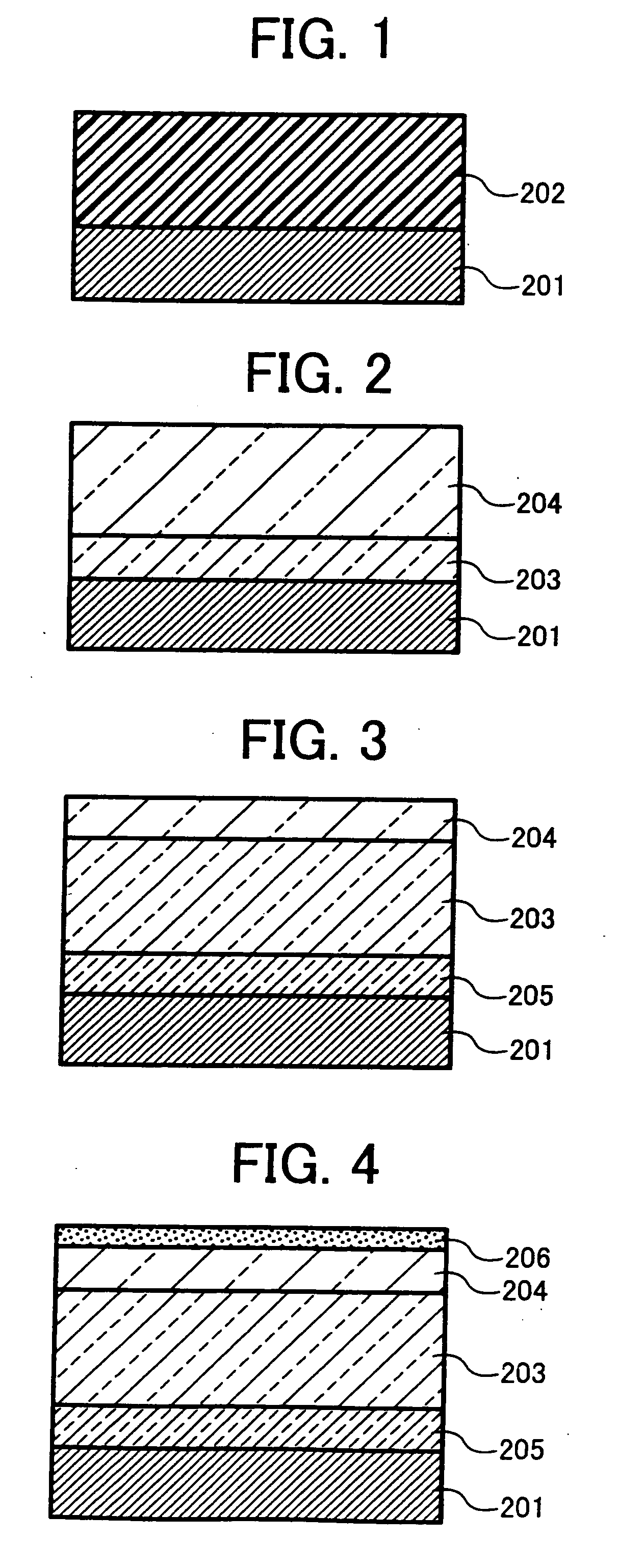
[0295] The following liquid application for an undercoating layer, for a charge generating layer and for a charge transport layer are applied to an aluminum cylinder having a diameter of 30 mm in this order by a dip coating method. Subsequent to drying, Image bearing member 1 is obtained, which has an undercoating layer having a thickness of 3.5 μm, a charge generating layer having a thickness of 0.2 μm and a charge transport layer having a thickness of 27 μm.

Liquid Application for Undercoating LayerTitanium dioxide powder400 partsMelamine resin 65 partsAlkyd resin120 parts2-butanone400 parts

[0296]

Liquid Application for Charge Generating LayerBisazo pigment represented by the following chemical structureChemical structure 112partsPolyvinylbutyral5parts2-butanone200partscyclohexanone400parts

[0297]

Liquid Application for Charge Transport LayerPolycarbonate (Z Polica, manufacturedby Teijin Chemicals Ltd.)Charge Transport Layer Represented by th...

manufacturing example 2

Manufacturing of Image Bearing Member 2

[0298] The liquid application prepared as described in Manufacturing Example 1, for an undercoating layer, for a charge generating layer and for a charge transport layer are applied to an aluminum cylinder having a diameter of 30 mm in this order by a dip coating method. Subsequent to drying, an undercoating layer having a thickness of 3.5 μm, a charge generating layer having a thickness of 0.2 μm and a charge transport layer having a thickness of 27 μm are obtained.

[0299] The following liquid application for a protective layer is applied to the charge transport layer by a spraying method (spraying gun: PieceCom PC308 with an air pressure of 2 kgf / cm2, manufactured by Olympos Co., Ltd.). Subsequent to drying at 150° C. for 60 minutes, Image bearing member 2 having a protective layer having a thickness of 5 μm is obtained.

Preparation of Liquid Application for Protective Layer

[0300] The solution having the following components are placed in...

manufacturing example 3

Manufacturing of Image Bearing Member 3

[0301] Image bearing member 3 is manufactured in the same manner as in Manufacturing Example 1 except that a protective layer is formed using the following liquid application for a protective layer.

Liquid of Application for Protective LayerPFA resin particles (MPE-056, manufactured by Du pont3.5partsMitsui Fluorochemical Co., Ltd.Dispersion helper (Modiper F210, manufactured by NOF0.35partsCorporation)Polycarbonate (Z Polica, manufactured by Teijin Chemicals6.15partsLtd.)Tetrahydrofuran200partsCyclohexanone60parts


PUM

PropertyMeasurementUnit
Lengthaaaaaaaaaa
Fractionaaaaaaaaaa
Linear densityaaaaaaaaaa

Abstract

An image forming apparatus including an image bearing member having a static friction coefficient of from 0.1 to 0.3, a latent electrostatic image forming device, a developing device, and a cleaning device including a cleaning blade to remove remaining toner, in which the contact pressure of the cleaning blade to the image bearing member ranges from 1.5 to 10 g/cm, and the image bearing member and the cleaning blade satisfy the following relationships (1) and (2):
0.01 (kg)≦(Toff−T0)/r≦0.15 (kg)   Relationship (1)
1.2≦(Ton−T0)/(Toff−T0)<3.8,   Relationship (2)
wherein T0 (kgcm) represents the rotation torque of the image bearing member when the cleaning blade is not in contact therewith, Toff, the rotation torque when the cleaning blade contacts the image bearing member and the toner is not thereon, Ton, the rotation torque when the cleaning blade contacts the image bearing member and the toner is thereon for development, and r represents the radius of the image bearing member.

Description

BACKGROUND OF THE INVENTION [0001] 1. Field of the Invention [0002] The present invention relates to an image forming apparatus and its corresponding image forming method and process cartridge. More particularly, the present invention relates to an image forming apparatus using a cleaning blade to remove toner remaining on the surface of an image bearing member. [0003] 2. Discussion of the Background [0004] There are known methods of electrophotography. For example, Carson Process and its variations are widely applied in photocopiers and printers. Recently, image forming apparatuses adopting electrophotography have been improved in colorization, image quality and processing speed. [0005] There is a single drum type color image forming apparatus, which forms a color image in such a manner that multiple developing devices for multiple colors provided around an image bearing member (also referred to as a latent electrostatic image bearing member, an electrophotographic photoreceptor, a...

Claims


Application Information

Patent Timeline
IPC IPC(8): G03G15/00G03G21/00
CPCG03G5/0539G03G5/142G03G5/144G03G5/14704G03G5/14708G03G5/14726G03G21/0011G03G21/0035G03G2215/0119G03G2215/0129G03G21/105
Inventor NAKAMORI, HIDEO
Owner RICOH KK
Why Eureka
Try Eureka