Liquefaction system and method for NG (Natural Gas)

A natural gas and subsystem technology, applied in refrigeration and liquefaction, liquefaction, gas fuel and other directions, can solve the problems of high complexity and energy consumption of liquefaction system

Active Publication Date: 2013-05-01
PETROCHINA CO LTD +1
View PDF5 Cites 21 Cited by
  • Summary
  • Abstract
  • Description
  • Claims
  • Application Information

AI Technical Summary

Problems solved by technology

[0004] visible, figure 2 The existing mixed refrigerant liquefaction system shown in the figure liquefies NG. At least two cold boxes are required to meet the requirements. The two refrigerants in this technology work independently and are cooled independently, so the complexity of the entire liquefaction system and higher energy consumption

Method used


Image

  • Liquefaction system and method for NG (Natural Gas)
  • Liquefaction system and method for NG (Natural Gas)
  • Liquefaction system and method for NG (Natural Gas)

Examples


Embodiment Construction

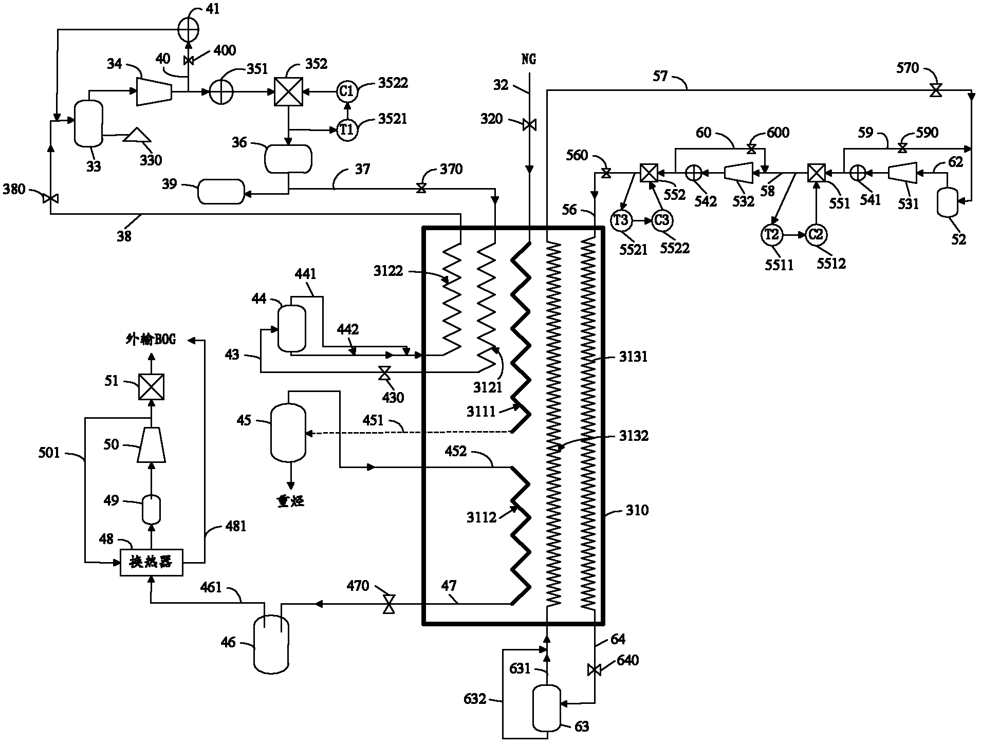
[0038] The principles and features of the present invention will be described below with reference to the accompanying drawings. The examples cited are only used to explain the present invention, and are not used to limit the scope of the present invention.

[0039] image 3 It is a structural diagram of the natural gas liquefaction system provided by the present invention. Such as image 3 As shown, the system includes:

[0040] Cold box 310; NG input pipe 32; No. 1 refrigerant liquefaction subsystem; No. 2 refrigerant liquefaction subsystem; heavy hydrocarbon separation tank 45; LNG storage tank 46;

[0041] The cold box 310 includes: NG pre-cooling channel 3111, NG deep cooling channel 3112, No. 1 refrigerant pre-cooling channel 3121, No. 2 refrigerant pre-cooling channel 3131, No. 1 refrigerant cooling channel 3122, No. 2 refrigerant cooling channel 3132 ;

[0042] The input end of the NG pre-cooling channel 3111 is connected to the NG input pipe 32 through the valve 320, the out...


PUM


Abstract

The invention relates to a liquefaction system and a liquefaction method for NG (Natural Gas). The system comprises a cold box, a supply pipe for supplying the NG to the cold box, a No.1 refrigerant liquefaction subsystem, a No.2 refrigerant liquefaction subsystem, a No.1 refrigerant cooling subsystem, a No.2 refrigerant cooling subsystem, a heavy hydrocarbon separation tank which is used for conducting gas-liquid separation to liquid heavy hydrocarbon and gas light hydrocarbon, and an LNG (Liquefied Natural Gas) storage tank which is used for storing LNG obtained through liquefaction, wherein the cold box comprises an NG precooling passage which is connected with the heavy hydrocarbon separation tank and is used for supplying the NG; an NG deep cooling passage which is connected with the LNG storage tank and is used for supplying the gas light hydrocarbon; a No.1 refrigerant precooling passage and a No.2 refrigerant precooling passage which are used for respectively supplying and cooling high-pressure No.1 refrigerant and high-pressure No.2 refrigerant which are respectively supplied by the No.1 refrigerant liquefaction subsystem the No.2 refrigerant liquefaction subsystem, and are used for respectively supplying the cooled high-pressure No.1 refrigerant and the cooled high-pressure No.2 refrigerant to the No.1 refrigerant cooling subsystem and the No.2 refrigerant cooling subsystem; and a No.1 refrigerant cooling passage and a No.2 refrigerant cooling passage which are used for respectively supplying low-temperature No.1 refrigerant and low-temperature No.2 refrigerant which are respectively supplied by the No.1 refrigerant cooling subsystem and the No.2 refrigerant cooling subsystem to cool the NG, high-temperature No.1 refrigerant and high-temperature No.2 refrigerant. By adopting the technical scheme, the complexity and the energy consumption of the system can be reduced.

Description

Technical field [0001] The invention relates to the technical field of natural gas liquefaction, in particular to a natural gas liquefaction system and method. Background technique [0002] The cold box used in the existing mixed refrigerant refrigeration process is of the wound tube type, and its structure is as figure 1 As shown, a tube core tube 102 is fixed inside the shell 101, and the refrigerant delivery channel 103 and the NG delivery channel 104 for conveying normal temperature refrigerant and NG are cross-wound on the tube core tube 102. The shell 101 and the refrigerant delivery channel 103. The space between the NG conveying passage 104 is the shell side, and the low-temperature refrigerant flows from top to bottom on the shell side. In this way, the normal temperature refrigerant and NG conveyed in the refrigerant conveying passage 103 and the NG conveying passage 104 are It exchanges heat with the low-temperature refrigerant outside the channel. The low-temperature ...

Claims


Application Information

Patent Timeline
Patent Type & Authority Applications(China)
IPC IPC(8): F25J1/02C10L3/10
Inventor 李卓燕白改玲王红宋媛玲
Owner PETROCHINA CO LTD
Why Eureka
Try Eureka