Ultra-fast boriding of metal surfaces for improved properties

a technology of electrochemical boriding and metal surfaces, applied in the direction of metallic material coating process, solid-state diffusion coating, coating, etc., can solve the problems of thinning down or wear out after repeated use, and achieve the effects of short processing time, desirable mechanical properties, and fast boriding

Inactive Publication Date: 2010-01-28
UCHICAGO ARGONNE LLC
View PDF3 Cites 25 Cited by
  • Summary
  • Abstract
  • Description
  • Claims
  • Application Information

AI Technical Summary

Benefits of technology

[0013]The present invention provides a method for producing metallic products with hard boride layers for a variety of mechanical and erosion resistant applications. The preferred method involves preparation of a molten electrolyte consisting of about 90 wt. % borates of alkaline and alkaline earth elements (such as borax) and about 10 wt. % carbonates of alkaline and alkaline-earth elements (such as sodium and / or calcium carbonate) or sodium chloride. Addition of small amounts (0.1 to 5 wt. %) of other halides (chlorides, fluorides, and iodides, etc.) of alkaline and / or alkaline-earth elements (like, LiCl, NaCl, CaCl2) can have positive effects as electrolyte enhancers. Oxides, hydroxides, and carbonates of such elements may also be used to control the viscosity and melting point of the electrolyte. Furthermore, using at least one of a high frequency induction furnace, external agitation, mixing of electrolyte or vibrating / shaking of the work piece holder can help overcome diffusion barriers in the electrochemical process and thus help achieve fast boriding and thick boride layers (about 100 micrometers or more in the case of low carbon steels) with desirable mechanical properties in short processing times (for example, less than an hour). Such a procedure can also result in a more uniform boride layer thickness on the surfaces of odd-shaped or intricate work pieces.
[0014]In electrochemical boriding, graphite is often used as the crucible material. The same graphite crucible can also serve as the anode of the electrochemical cell. Due to the high temperature nature of the boriding process, the graphite crucible or anode may undergo oxidation and hence thin down or wear out after repeated uses. As an alternative approach, in our process, we can also use the metallic and / or borided forms of titanium, aluminum, zirconium, hafnium, vanadium, niobium, tantalum, nickel, molybdenum, chromium, tungsten, cobalt, iron and their alloys as anodes and / or crucible materials. Specifically, we can form a thin boride layer on the surface of these metals by reverse polarization (i.e., by making the crucible a cathode) and then switch back to the regular boriding practice by changing the polarity, switching the cathode with the anode again. In particular, the boride layers that form on titanium (and its alloys) have excellent resistance to high temperature corrosion and oxidation. They are also electrically conductive, hence they can be an ideal choice for the industrial-scale boriding operations. Alternatively, iron and its alloys can also be borided first and then used as crucibles and / or anodes. Iron borides are also electrically conductive (this is why they form thick boride layers during our boriding process). In fact, reverse polarization of anodes and / or crucibles can be done as needed if the boride layer thickness on the crucible or the anode surface is reduced or there is a need for repair of a thinned down or worn area. Such a practice will ensure long durability and hence low cost.
[0015]The thickness and composition (e.g., type of boride, such as FeB or Fe2B, or Fe3B, diffusion layer) of borided surface layers can be controlled to achieve performance and durability requirements of a given application. For certain applications, Fe2B could be a preferred phase due to its superior strength and toughness. During the boriding process, the boriding temperature and / or current density may be maintained low to achieve only this phase over the other. Alternatively, one can also keep the boriding duration short but leave the work pieces in the molten electrolyte for a longer duration to allow excess boron to diffuse or distribute evenly within the structure and hence stabilize the Fe2B phase over the FeB phase. Nano-to-micro scale boride phases can also be produced in a given surface region by selectively reacting diffusing boron atoms with secondary phases and / or alloying elements within that region. This allows achieving multiple objectives, such as improved mechanical properties without degrading thermal and / or electrical properties of the base material. It is also possible to partially or selectively boride the surface or a region of a work piece by various masking methods as will be discussed in Examples.

Problems solved by technology

Due to the high temperature nature of the boriding process, the graphite crucible or anode may undergo oxidation and hence thin down or wear out after repeated uses.

Method used


Image

  • Ultra-fast boriding of metal surfaces for improved properties
  • Ultra-fast boriding of metal surfaces for improved properties
  • Ultra-fast boriding of metal surfaces for improved properties

Examples


example 1

The Effect of Boriding Time on Boron Layer Thickness

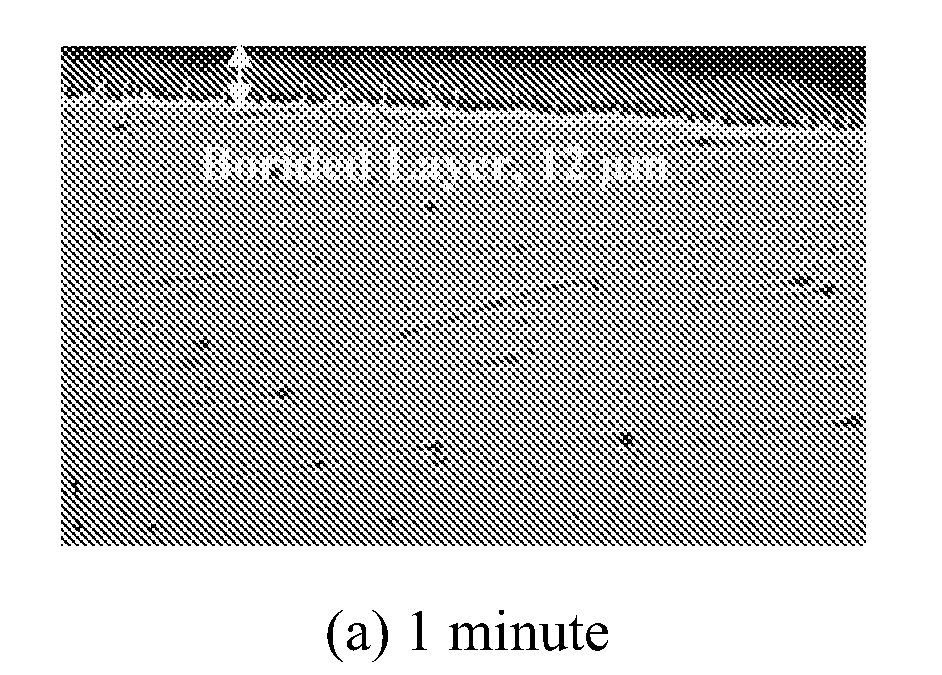
[0057]The following Tables I and II show the relationship between total boride and FeB layer thickness and boriding time. (Electrolyte composition: % 10 NaCl+% 90 Na2B4O7; Current density: 200 mA / cm2; Temperature: 900° C.). After the electrochemical boriding treatment, by switching off the power to electrodes and leaving the borided sample in the molton electrolyte for an additional time period (e.g., as short as 10 minutes and as long as 2 hours), the top FeB layer may be eliminated.

TABLE ITime1 minute5 minutes10 minutes15 minutesTotalTotalTotalTotalBoridedFeBBoridedFeBBoridedFeBBoridedFeBLayerLayerLayerLayerLayerLayerLayerLayerThicknessThicknessThicknessThicknessThicknessThicknessThicknessThickness(μm)(μm)(μm)(μm)(μm)(μm)(μm)(μm)Maximum18.80N / A39.7723.6045.1120.8962.3034.25Minimum6.587.148.5930.0014.2340.8520.00Measured15.7530.3616.6041.5016.8756.7623.04Thickness7.2026.0521.5840.1317.6951.3637.22Values14.5016.7040.0716.2361.758.5...

example 2

Effect of Current Density on Boride Layer Thickness

[0058]In another example, the relationship was determined between current density and total borided and FeB layer thickness, as described in Table III below. (Electrolyte composition: % 20 NaCl+% 80 Na2B4O7; Total process time: 1 hour; Temperature: 900° C.). The graphical appearance of boride layer thickness versus current density is shown in FIG. 11.

TABLE IIICurrent Density50 mA / cm2100 mA / cm2200 mA / cm2300 mA / cm2700 mA / cm2TotalTotalTotalTotalTotalBoridedFeBBoridedFeBBoridedFeBBoridedFeBBoridedFeBLayerLayerLayerLayerLayerLayerLayerLayerLayerLayerThicknessThicknessThicknessThicknessThicknessThicknessThicknessThicknessThicknessThickness(μm)(μm)(μm)(μm)(μm)(μm)(μm)(μm)(μm)(μm)Maximum52.68N / A110.9660.12124.0857.24112.8068.31142.6698.624Minimum20.0455.0012.4276.3327.7858.4128.6170.0023.66Measured49.4097.0050.00109.8329.62111.3665.9796.0067.71Thickness50.82103.0035.8083.4248.9269.67123.4285.24Values48.0099.6442.9084.3451.59107.35120.0080.0...

example 3

Relationship Between Electrochemical Cell Potential and Current Density in Molten Electrolyte

[0059]The relationship between cell potential and the current density (20% NaCl+80% Na2B4O7, 1 hour, 900° C.) is illustrated in FIG. 12 from a set of measurements and cross sectional micrographs of the boride layers produced at different current densities are shown in FIGS. 13A-13E for various current densities for an electrolyte of 20% NaCl plus 80% Na2B4O7 at 1 hour and 900° C. Cell potential directly related with resistivity of electrolyte, in general 1.5-6V cell potential is the expected range for the working current density applications. Depending on electrolyte resistance cell potential can be as high as 20V. In addition to direct current (DC), the cell potential may be applied in the radio-frequency (RF) (MHz range), bi-polar pulse DC (Hz to kHz range, different wave forms; e.g. square, sine, triangle sawtooth etc.), and high power impulse modes, or any other modes available. In parti...


PUM

PropertyMeasurementUnit
weight percentaaaaaaaaaa
depthsaaaaaaaaaa

Abstract

A method of ultra-fast boriding of a metal surface. The method includes the step of providing a metal component, providing a molten electrolyte having boron components therein, providing an electrochemical boriding system including an induction furnace, operating the induction furnace to establish a high temperature for the molten electrolyte, and boriding the metal surface to achieve a boride layer on the metal surface.

Description

CROSS REFERENCE TO RELATED PATENT APPLICATIONS[0001]The present application claims priority to U.S. Provisional Patent Application No. 61 / 059,177, filed Jun. 5, 2008 incorporated herein by reference in its entirety.STATEMENT OF GOVERNMENT INTEREST[0002]The United States Government has certain rights in this invention pursuant to Contract No. W-31-109-ENG-38 between the United States Government and The University of Chicago and / or pursuant to Contract No. DE-AC02-06CH11357 between the United States Government and UChicago Argonne, LLC representing Argonne National Laboratory.FIELD OF THE INVENTION[0003]This invention is directed to an ultra-fast surface treatment method that results in hard, wear, corrosion and erosion resistant, and low-friction surface layers on metallic substrates. More particularly, the present invention relates to an ultra fast electrochemical boriding technique which can lead to dramatic improvements in the mechanical and tribological properties of treated meta...

Claims


Application Information

Patent Timeline
Patent Type & Authority Applications(United States)
IPC IPC(8): C23C8/68C22C14/00
CPCC23C8/42
Inventor TIMUR, SERVETKARTAL, GULDEMERYILMAZ, OSMAN L.ERDEMIR, ALI
Owner UCHICAGO ARGONNE LLC
Why Eureka
Try Eureka