Ultra-fast boriding of metal surfaces for improved properties
a metal surface and ultra-fast technology, applied in the direction of surface reaction electrolytic coating, solid-state diffusion coating, coating, etc., can solve the problems of thinning down or wear out after repeated use, and achieve the effects of short processing time, desirable mechanical properties, and fast boriding
- Summary
- Abstract
- Description
- Claims
- Application Information
AI Technical Summary
Benefits of technology
Problems solved by technology
Method used
Image
Examples
example 1
The Effect of Boriding Time on Boron Layer Thickness
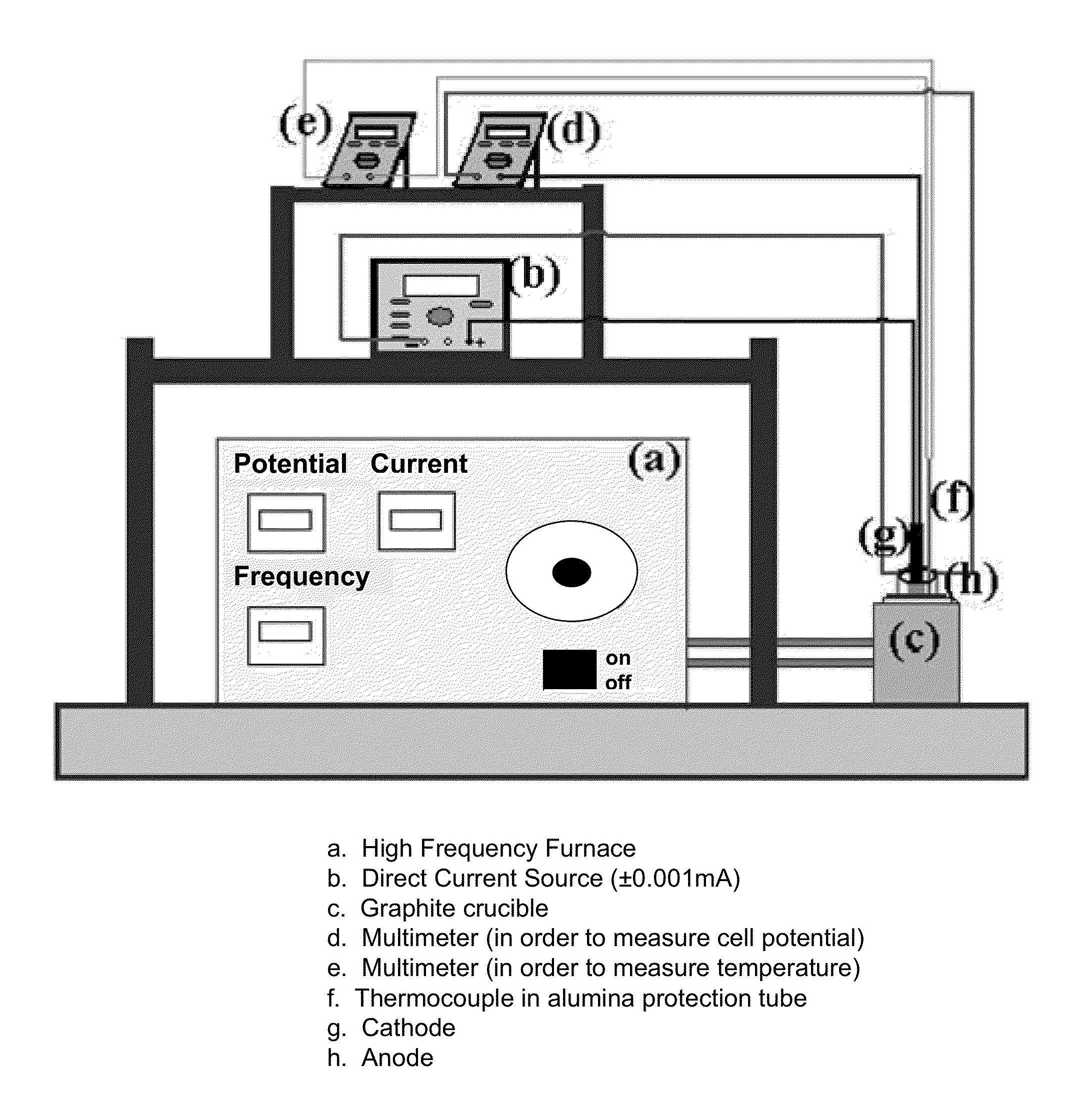
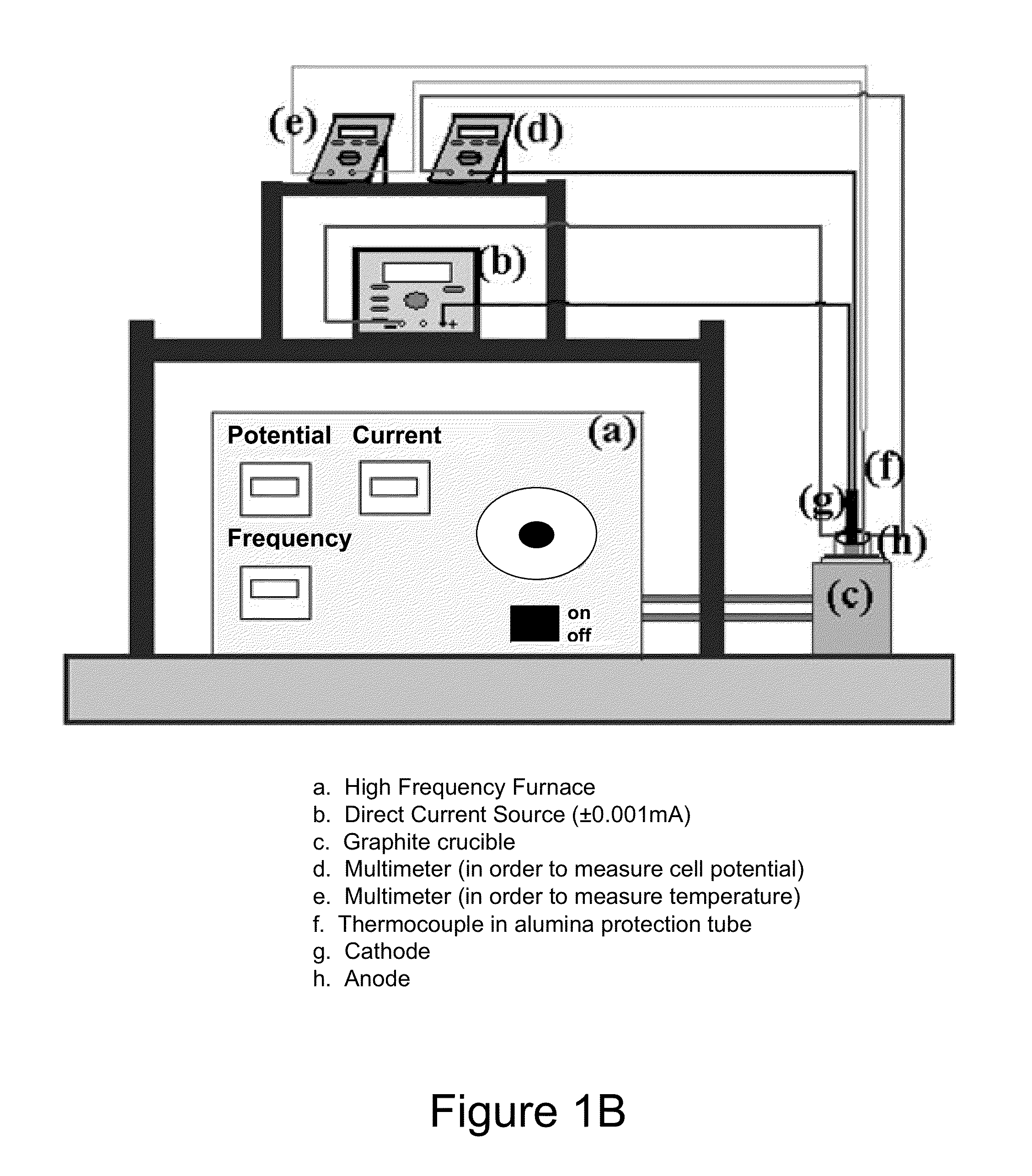
[0058]The following Tables I and II show the relationship between total boride and FeB layer thickness and boriding time. (Electrolyte composition: % 10 NaCl+% 90 Na2B4O7; Current density: 200 mA / cm2; Temperature: 900° C.). After the electrochemical boriding treatment, by switching off the power to electrodes and leaving the borided sample in the molton electrolyte for an additional time period (e.g., as short as 10 minutes and as long as 2 hours), the top FeB layer may be eliminated.
[0059]
TABLE ITime1 minute5 minutes10 minutes15 minutesTotalTotalTotalTotalBoridedFeBBoridedFeBBoridedFeBBoridedFeBLayerLayerLayerLayerLayerLayerLayerLayerThicknessThicknessThicknessThicknessThicknessThicknessThicknessThickness(μm)(μm)(μm)(μm)(μm)(μm)(μm)(μm)Maximum18.80N / A39.7723.6045.1120.8962.3034.25Minimum6.587.148.5930.0014.2340.8520.00Measured15.7530.3616.6041.5016.8756.7623.04Thickness7.2026.0521.5840.1317.6951.3637.22Values14.5016.7040.0716.2361...
example 2
Effect of Current Density on Boride Layer Thickness
[0061]In another example, the relationship was determined between current density and total borided and FeB layer thickness, as described in Table III below. (Electrolyte composition: % 20 NaCl+% 80 Na2B4O7; Total process time: 1 hour; Temperature: 900° C.). The graphical appearance of boride layer thickness versus current density is shown in FIG. 11.
[0062]
TABLE IIICurrent Density50 mA / cm2100 mA / cm2200 mA / cm2300 mA / cm2700 mA / cm2TotalTotalTotalTotalTotalBoridedFeBBoridedFeBBoridedFeBBoridedFeBBoridedFeBLayerLayerLayerLayerLayerLayerLayerLayerLayerLayerThicknessThicknessThicknessThicknessThicknessThicknessThicknessThicknessThicknessThickness(μm)(μm)(μm)(μm)(μm)(μm)(μm)(μm)(μm)(μm)Maximum52.68N / A110.9660.12124.0857.24112.8068.31142.6698.624Minimum20.0455.0012.4276.3327.7858.4128.6170.0023.66Measured49.4097.0050.00109.8329.62111.3665.9796.0067.71Thickness50.82103.0035.8083.4248.9269.67123.4285.24Values48.0099.6442.9084.3451.59107.35120....
example 3
Relationship Between Electrochemical Cell Potential and Current Density in Molten Electrolyte
[0063]The relationship between cell potential and the current density (20% NaCl+80% Na2B4O7, 1 hour, 900° C.) is illustrated in FIG. 12 from a set of measurements and cross sectional micrographs of the boride layers produced at different current densities are shown in FIGS. 13A-13E for various current densities for an electrolyte of 20% NaCl plus 80% Na2B4O7 at 1 hour and 900° C. Cell potential directly related with resistivity of electrolyte, in general 1.5-6V cell potential is the expected range for the working current density applications. Depending on electrolyte resistance cell potential can be as high as 20V. In addition to direct current (DC), the cell potential may be applied in the radio-frequency (RF) (MHz range), bi-polar pulse DC (Hz to kHz range, different wave forms; e.g. square, sine, triangle sawtooth etc.), and high power impulse modes, or any other modes available. In parti...
PUM
| Property | Measurement | Unit |
|---|---|---|
| temperatures | aaaaa | aaaaa |
| current density | aaaaa | aaaaa |
| distance | aaaaa | aaaaa |
Abstract
Description
Claims
Application Information
 - R&D
- Intellectual Property
- Life Sciences
- Materials
- Tech Scout
- Unparalleled Data Quality
- Higher Quality Content
- 60% Fewer Hallucinations
Browse by: Latest US Patents, China's latest patents, Technical Efficacy Thesaurus, Application Domain, Technology Topic, Popular Technical Reports.
© 2025 PatSnap. All rights reserved.Legal|Privacy policy|Modern Slavery Act Transparency Statement|Sitemap|About US| Contact US: help@patsnap.com


