Reflector, sidelight type backlighting apparatus and reflector substrate

a backlighting apparatus and reflector technology, applied in the direction of mirrors, instruments, prisms, etc., can solve the problems of irregular luminance, loss of diffuse reflection components, and insufficient illumination as a whole, and achieve the effect of improving brightness

Inactive Publication Date: 2003-07-24
MITSUI CHEM INC
View PDF3 Cites 23 Cited by
  • Summary
  • Abstract
  • Description
  • Claims
  • Application Information

AI Technical Summary

Benefits of technology

0107] In the sidelight type backlighting apparatus according to the invention, the use of a reflector 1 produced by the methods above prevents the generation of uneven br

Problems solved by technology

However, since such an uneven reflection member yields almost no regular reflection component, the brightness obtained as a result is uniform, but there is a problem that the luminance as a whole is still insufficient.
Further, although the luminance can be improved in the case a sheet comprising aluminum vapor-deposited on a transparent or light transmitting PET film is used, the diffuse reflection component is lost,

Method used


Image

  • Reflector, sidelight type backlighting apparatus and reflector substrate
  • Reflector, sidelight type backlighting apparatus and reflector substrate
  • Reflector, sidelight type backlighting apparatus and reflector substrate

Examples


example 1

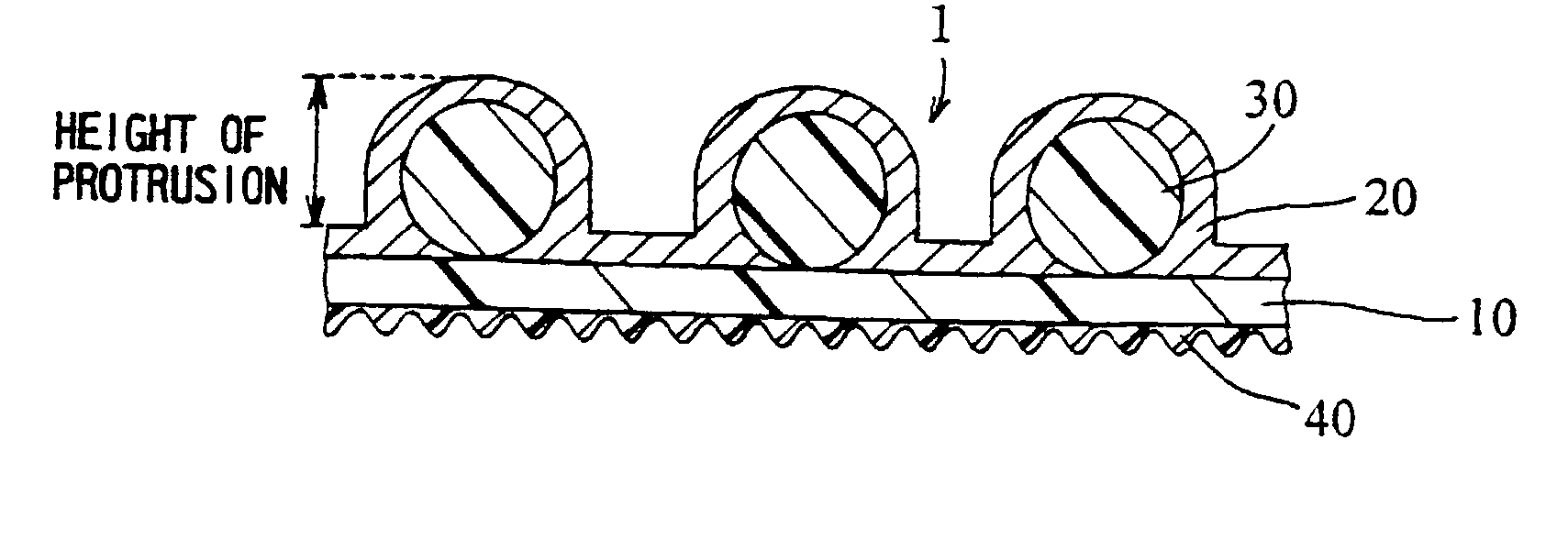
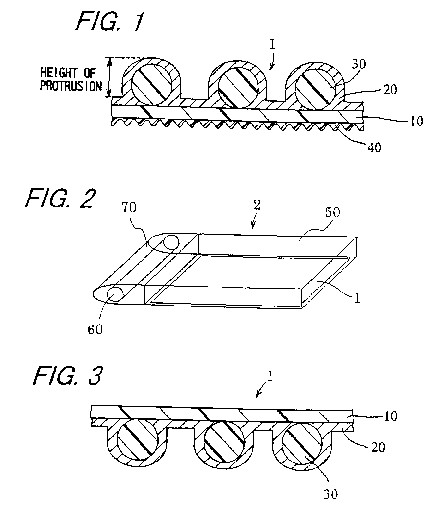
[0110] As the protrusions, acrylic particles 30 .mu.m in mean particle diameter were blended at an amount of 6.0 wt % in an acrylic resin binder, and a solution was prepared by adding a solvent comprising toluene and methyl ethyl ketone in such a manner that the solution may contain 24 wt % of solid matter. The resulting solution was applied to a 188-.mu.m thick PET film to obtain protrusions on the surface A. Then, acrylic particles 1.5 .mu.m in mean particle diameter were blended at an amount of 2.0 wt % in an acrylic resin binder, and a solution was prepared by adding a solvent comprising toluene and methyl ethyl ketone in such a manner that the solution may contain 15 wt % of solid matter. The resulting solution was applied to a PET film to obtain a smoothed surface on the surface B.

[0111] Subsequently, a zinc oxide layer was formed at a film thickness of 5 nm on the surface A side by means of DC magnetron sputtering using zinc oxide (purity: 99.9%) doped with 2% of Al.sub.2O.su...

example 2

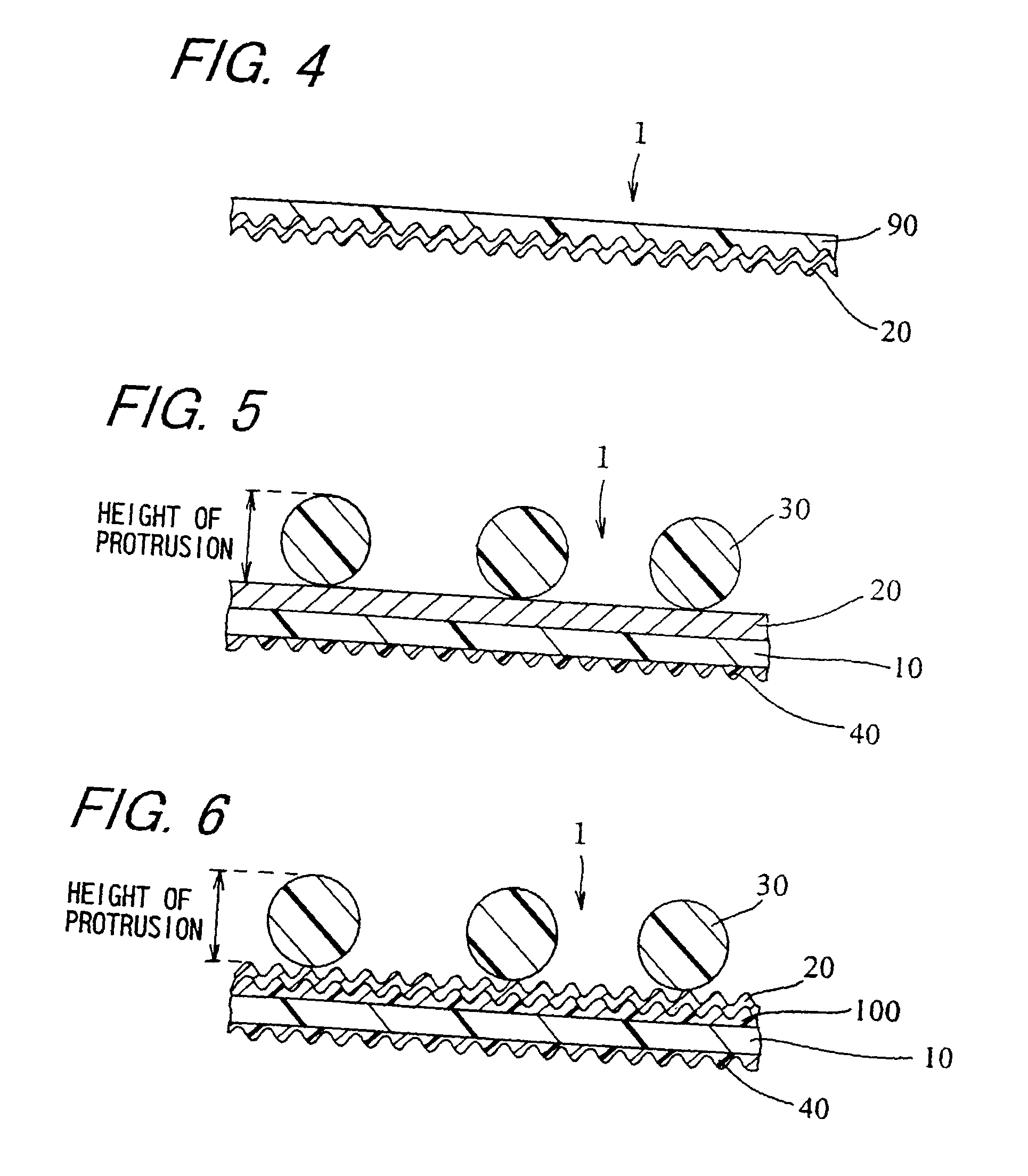
[0112] As the protrusions, acrylic particles 35 .mu.m in mean particle diameter were blended together with an acrylic resin binder at an amount of 5.5 wt % each, and a solution was prepared by adding a solvent comprising toluene and methyl ethyl ketone in such a manner that the solution may contain 24 wt % of solid matter. Then, a 188-.mu.m thick PET film one surface of which was subjected to sand blasting treatment was prepared, and the resulting solution was applied to the non-treated surface of the film to obtain protrusions on this non-treated surface (surface A). Then, a reflection layer 20 was formed in conformity with the condition of Example 1, whereby a reflector 1 was obtained. Subsequently, measurements were conducted in a manner similar to that described in Example 1 to obtain the following results: a total reflectance of 93.8%; a diffuse reflectance of 6.6%; a diffusivity of 7.0%; an average value for the height of the surface A side protrusions of 28.8 .mu.m; an averag...

example 3

[0117] As the protrusions, particles of acrylic resin (manufactured by Negami Kogyo Co., Ltd.) 5 .mu.m in mean particle diameter were blended together with an acrylic resin (manufactured by Mitsui Chemicals Inc., trademark Almatex) binder in a solvent comprising toluene and methyl ethyl ketone in such a manner that the resulting solution may contain 35 wt % of solid matter and that the particles may account for 10 wt % of the solid matter. Then, the resulting solution was applied to a 50-.mu.m thick PET film to obtain a protrusion layer. Subsequently, on the protrusion layer, a 5-nm thick layer of zinc oxide was formed as a light transmitting oxide film layer by means of DC magnetron sputtering using zinc oxide (99.9% purity) doped with 2% of Al.sub.2O.sub.3 as the target and 99.5% pure argon as the sputtering gas. Then, without taking the film out from the sputtering apparatus, a 200-nm thick layer of silver was formed similarly as a silver layer by means of DC magnetron sputtering...


PUM


Abstract

An object of the invention is to provide a sidelight type backlighting apparatus having high brightness, which is yet reduced in uneven brightness, and to provide a reflector substrate having a surface profile necessary for obtaining such apparatus and a reflector having high brightness and long durability in which the reflector substrate is implemented. A buffer against strain is formed by providing space by protrusions or the like between a light guiding plate of a planar light source apparatus and a reflecting surface of a reflection sheet provided on one main surface of the light guiding plate. Further, a base layer, a metallic layer mainly containing silver, and a light transmitting oxide layer are laminated on the substrate in this order to form a reflection layer.

Description

[0001] The present invention relates to a reflector having high reflectivity and brightness, which is yet reduced in uneven brightness, to a sidelight type backlighting apparatus using the same, applied to a liquid crystal display apparatus, and to a reflector substrate.[0002] Liquid crystal displays are thinner and are more compact as compared with CRT (Cathode Ray Tube) displays known heretofore, and because they operate at lower voltage, consume less power, and hence are energy saving, they are used not only as displays of small to medium size apparatuses, but also in a wider field.[0003] The liquid crystal displays widely used at present are transmission type liquid crystal displays using backlighting for the light source. The display clarity of the liquid crystal display owes not only on the performance of the liquid crystal itself, but also on the performance of the backlighting. Due to the recent indispensable requirements on further lightweight and thinner liquid crystal dis...

Claims


Application Information

Patent Timeline
IPC IPC(8): F21V8/00G02B5/02
CPCG02B5/0221G02B5/0226G02B6/0055G02B6/0038G02B5/0284G02F1/1335
Inventor YOSHIDA, HIROTAKAFUKUDA, SHINISHIKAWA, HIROSHITANABE, MASARU
Owner MITSUI CHEM INC
Why Eureka
Try Eureka