Scan-based state save and restore method and system for inactive state power reduction

a state save and restore and inactive state technology, applied in the field of power management, can solve the problems of inability to use the situation, device completely drained of battery power, and much higher leakage curren

a state save and restore and inactive state technology, applied in the field of power management, can solve the problems of inability to use the situation, device completely drained of battery power, and much higher leakage curren

US7058834B2Inactive Publication Date: 2006-06-06AVENPORE PROPERTIES LLC

Image

  • Scan-based state save and restore method and system for inactive state power reduction
  • Scan-based state save and restore method and system for inactive state power reduction
  • Scan-based state save and restore method and system for inactive state power reduction

Examples


Embodiment Construction

[0028]A scan-based state save and restore method and system for inactive state power reduction are described. In the following description, for the purposes of explanation, numerous specific details are set forth in order to provide a thorough understanding of the present invention. It will be apparent, however, to one skilled in the art that the present invention may be practiced without these specific details. In other instances, well-known structures and devices are shown in block diagram form in order to avoid unnecessarily obscuring the present invention.

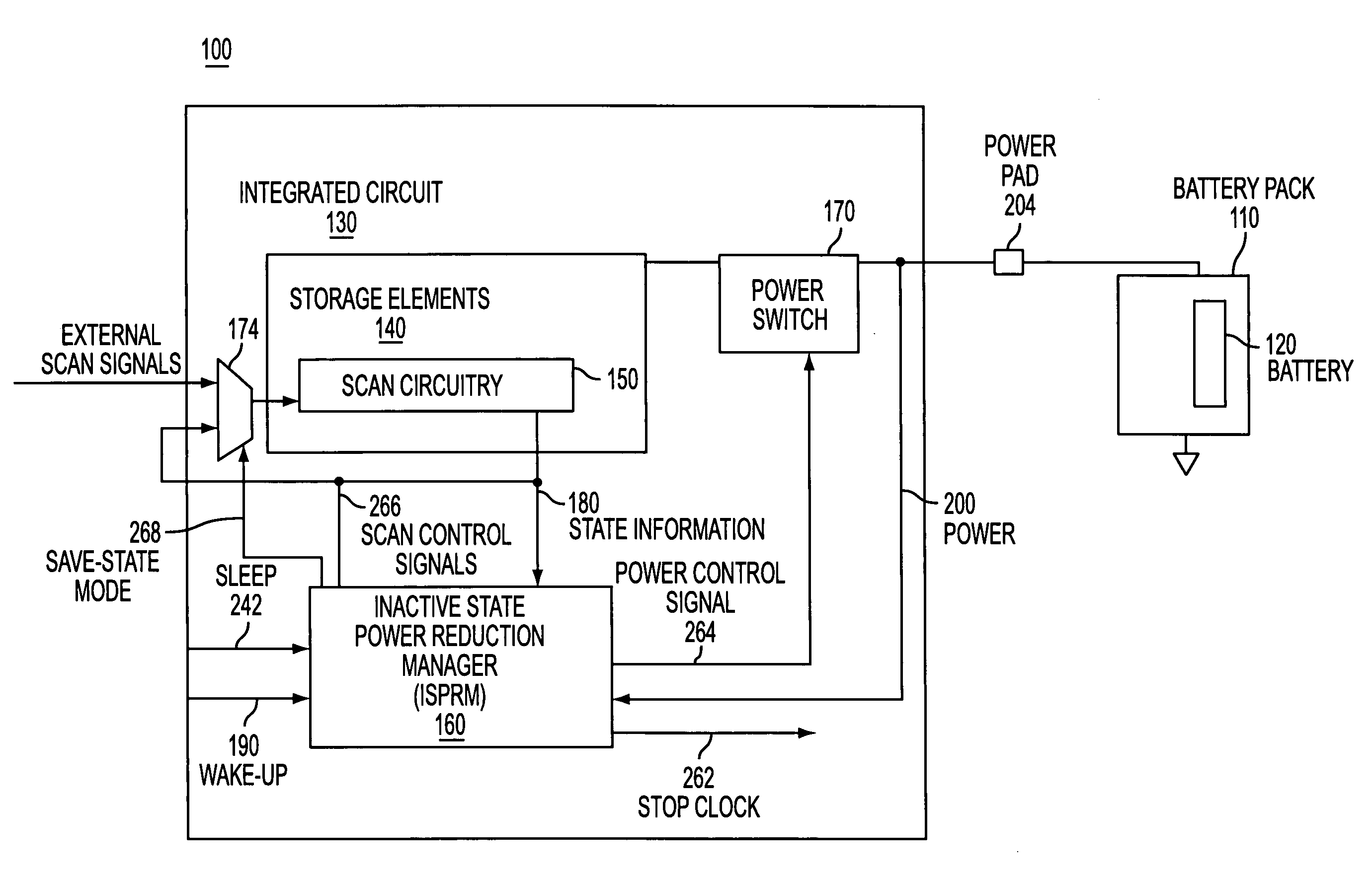
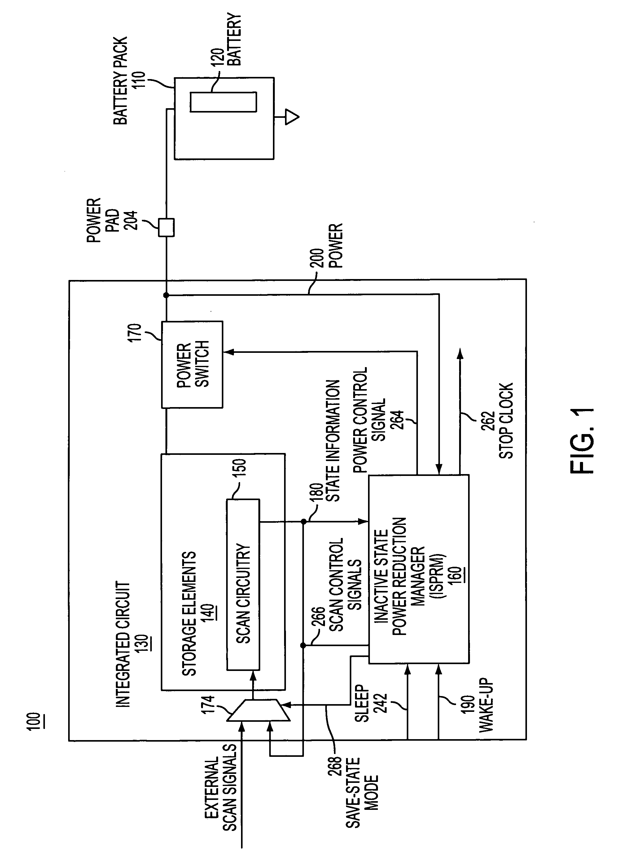
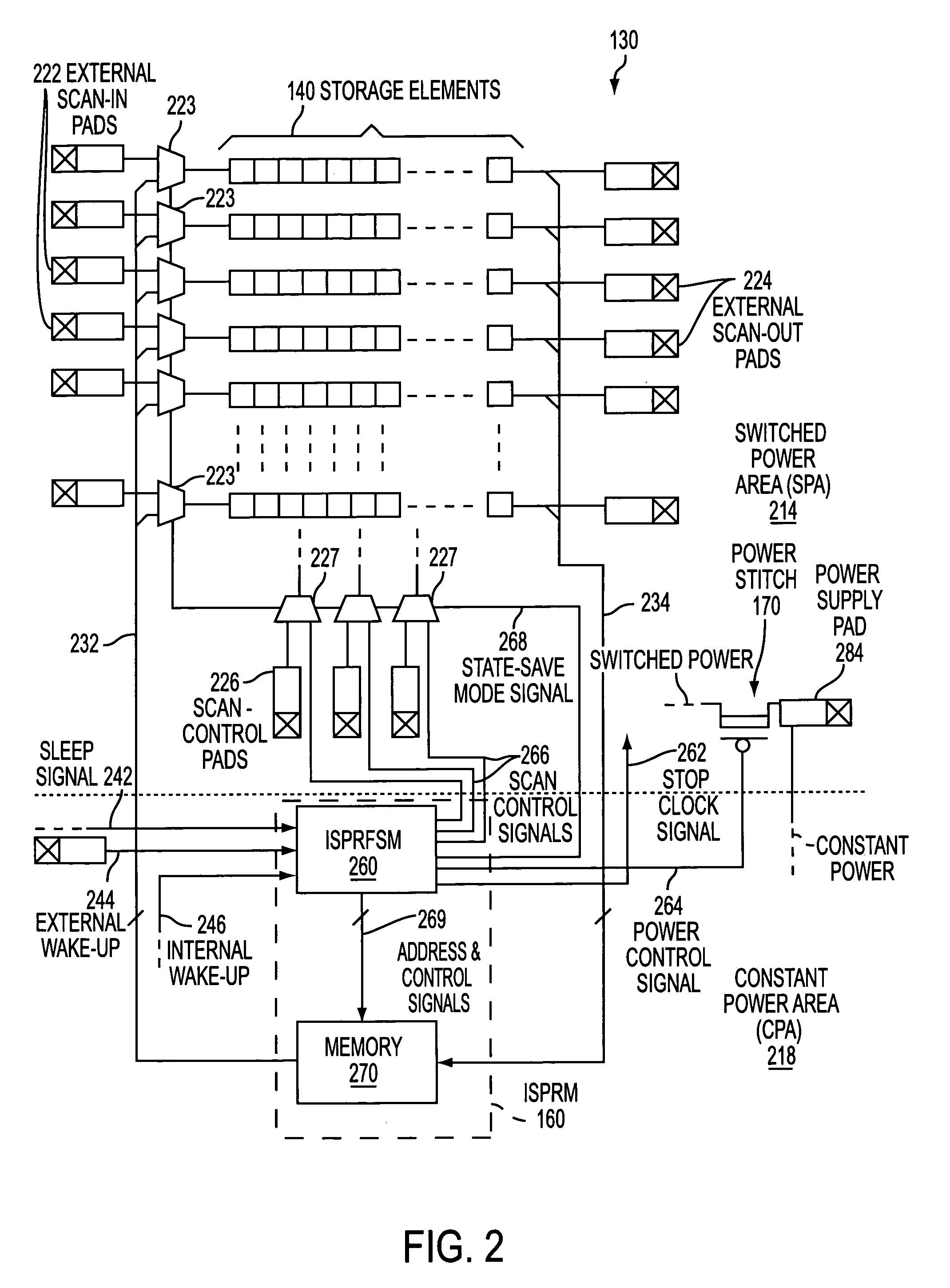
[0029]One aspect of the present invention is the use of test circuitry (e.g., scan circuitry) for accessing state information from the storage elements of a circuit, and the use of test circuitry to restore state information to the storage elements of the circuit. In this manner, the power can be disconnected from a portion of the circuit to reduce power consumption during periods of inactivity without the loss of state informa...


PUM


Abstract

A scan-based state save and restore method and system for inactive state power reduction. An integrated circuit that has an inactive state has normal circuitry and scan circuitry. Upon receipt of a sleep signal, the state of the normal circuitry is accessed by employing scan circuitry. The state is then stored in a memory. The power is disconnected from the normal circuitry. Upon wake-up, the normal circuitry is re-connected to the power. The state of the circuit is accessed from the memory and restored to the normal circuitry by employing scan circuitry.

Description

FIELD OF THE INVENTION[0001]The present invention relates generally to power management, and more particularly, to a scan-based state save and state restore method and system for inactive state power reduction.BACKGROUND OF THE INVENTION[0002]Battery operated devices typically have some type of power management in order to conserve the battery power and extend the length of operation of the device before having to re-charge the batteries or otherwise replace the drained batteries with fresh batteries.[0003]For example, battery operated devices that include complimentary metal oxide semiconductor (CMOS) circuits can reduce battery drain during periods of inactivity by stopping the system clock signal that is provided to the CMOS integrated circuits (also commonly referred to as “chips”). Stopping the clock reduces power consumption without losing the state of the chip. The state is simply the current information when the clock is stopped that is needed to resume the current processes...

Claims


Application Information

Patent Timeline
06 Jun 2006
Publication
US7058834B2
IPC
G06F1/30; G06F1/32; H04N5/63
CPC
G06F1/32
Inventors
WOODS, PAUL RICHARD; MCDOUGAL, JAY DEAN