
Method for automatically sizing and biasing circuits by means of a database

Inactive Publication Date: 2006-06-06
CADENCE DESIGN SYST INC
View PDF7 Cites 13 Cited by
  • Summary
  • Abstract
  • Description
  • Claims
  • Application Information

AI Technical Summary

Benefits of technology

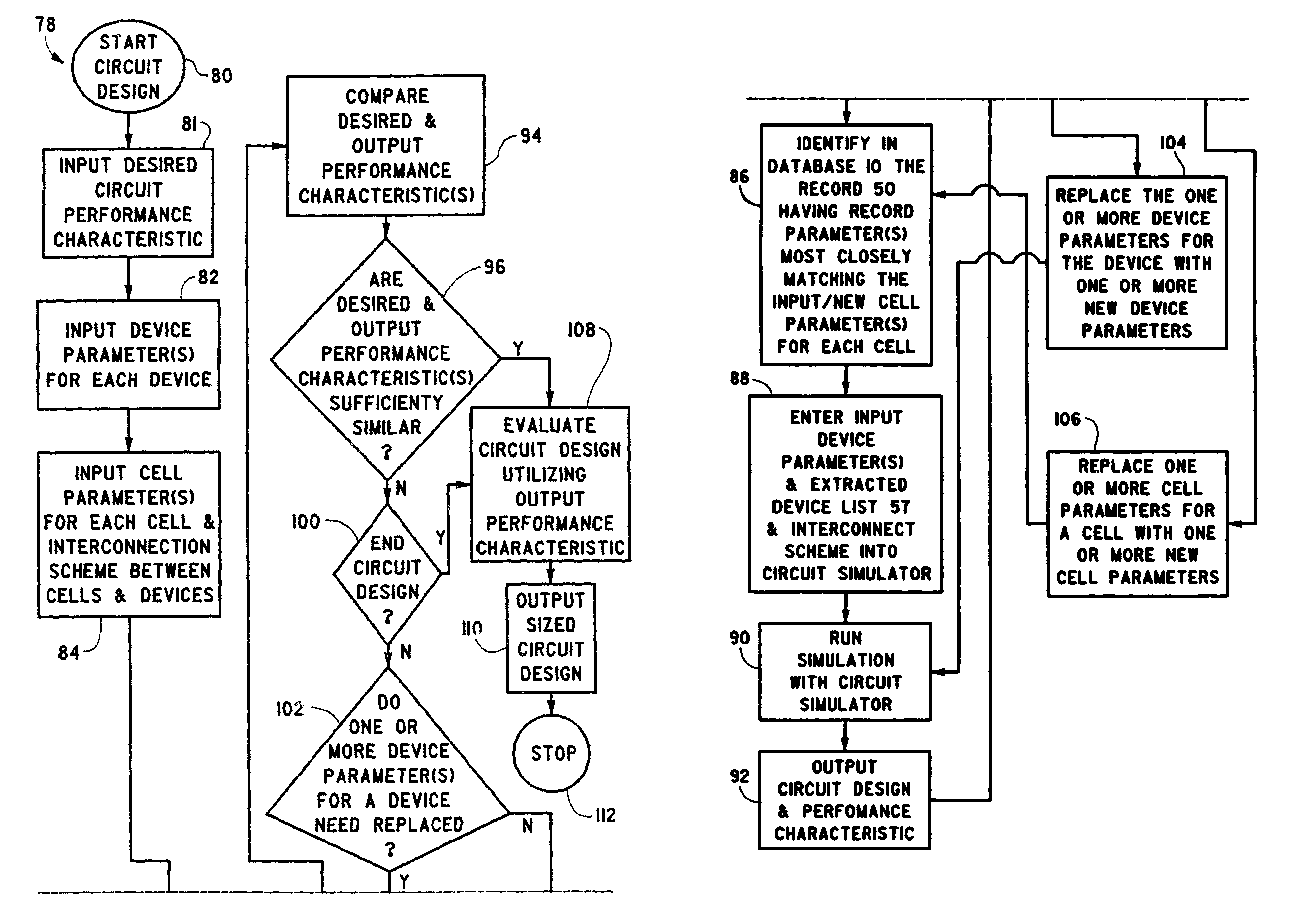
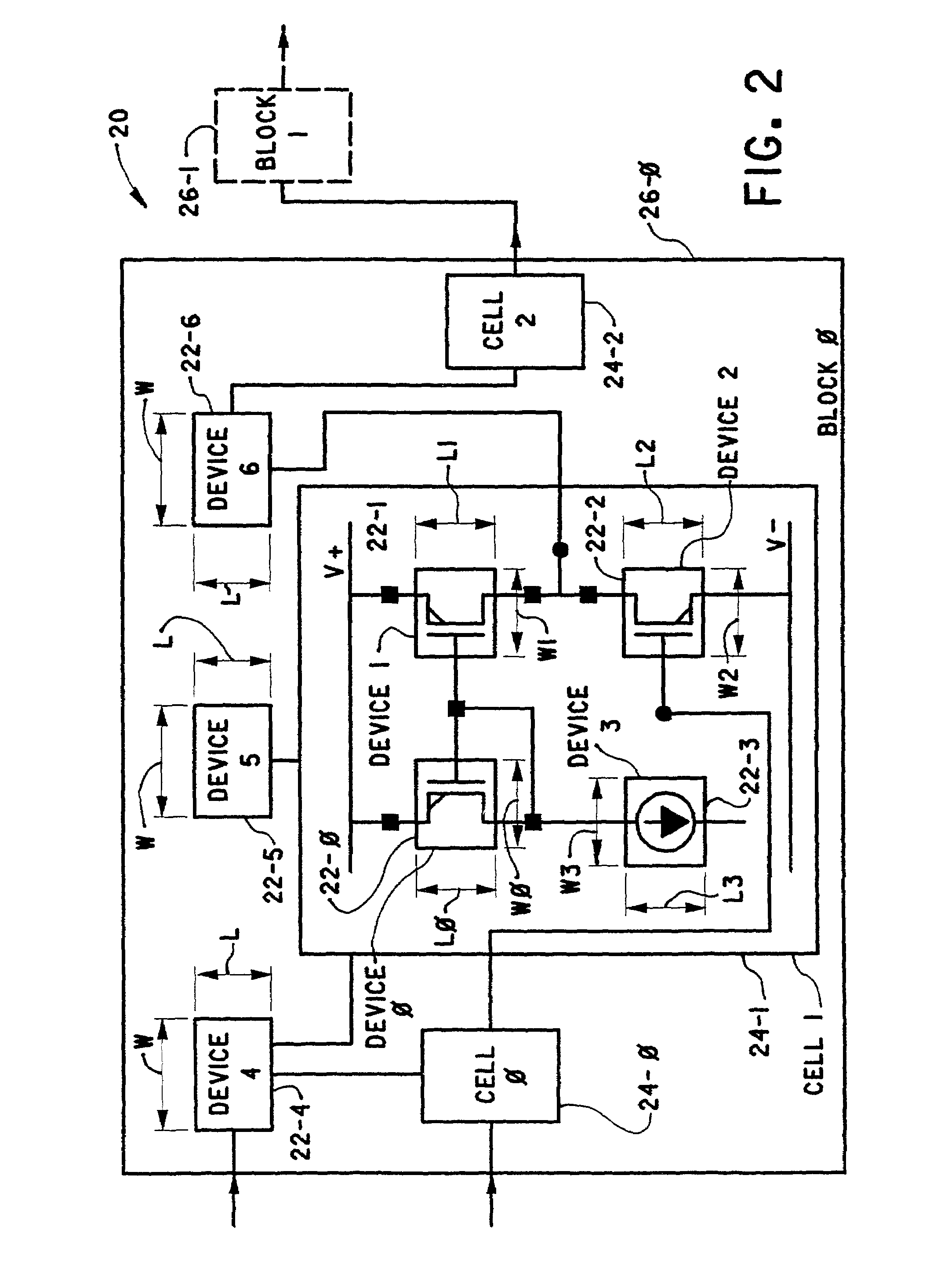
[0010]Accordingly, we have invented a method of automatically sizing and biasing a circuit. The method includes providing a database including a plurality of records related to cells that can be utilized to form an integrated circuit. Each record includes the data regarding devices included in a corresponding cell, an interconnecting scheme of the devices included in the corresponding cell and at least one cell parameter

Problems solved by technology

However, in more complex circuits, an interconnection of plural cells may be needed to form the circuit.
Redesign is typical because it is not easy to predict the performance of a design before detailed simulation, and detailed simulation requires that a design be well defined.
The main problems occur because accurately predicting the performance of cells before they are designed is difficult and error prone.

Method used


Image

  • Method for automatically sizing and biasing circuits by means of a database
  • Method for automatically sizing and biasing circuits by means of a database
  • Method for automatically sizing and biasing circuits by means of a database

Examples


Embodiment Construction

[0031]The present invention will be described with reference to the accompanying figures where like reference numbers correspond to like elements.

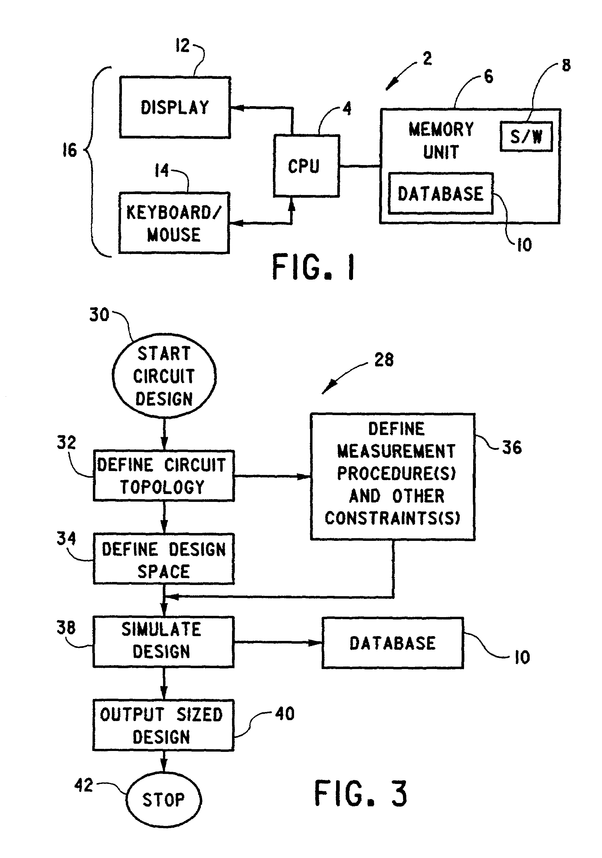
[0032]With reference to FIG. 1, the present invention is embodied in integrated circuit design software 8 which controls the operation of a computer 2 in a predetermined manner to implement the present invention. Computer 2 includes a CPU 4 which is coupled to a memory unit 6 which stores software 8 and a database 10, to be described hereinafter. Memory unit 6 includes one or more of RAM, ROM, magnetic data storage, optical data storage and the like required for the execution and operation of software 8 by CPU 4.

[0033]Computer 2 also includes a display 12 and a keyboard / mouse 14 which collectively act as a user interface 16 between computer 2 operating under the control of software 8 and a user of computer 2. Computer 2 is shown for the purpose of illustration and is not to be construed as limiting the invention.

[0034]With reference to FIG...


PUM


Abstract

In a method of automatically sizing and biasing a circuit, a database is provided including a plurality of records related to cells that can be utilized to form an integrated circuit. A cell parameter of a cell for a circuit is selected and compared to cell parameters residing in the records stored in the database. One record in the database is selected based upon this comparison and a performance characteristic of the circuit is determined from this record.

Description

CROSS REFERENCE TO RELATED APPLICATIONS[0001]This application claims the benefit of U.S. Provisional Patent Application Ser. No. 60 / 301,595, filed Jun. 28, 2001.BACKGROUND OF THE INVENTION[0002]1. Field of the Invention[0003]The present invention relates to sizing and biasing of devices utilized to form a circuit that satisfies a set of performance parameters.[0004]2. Description of Related Art[0005]Heretofore, custom integrated circuits were designed by interconnecting a plurality of devices such as transistors, resistors, capacitors, inductors, diodes, and the like to form cells. In a simple custom integrated circuit, one cell could form the entire circuit. However, in more complex circuits, an interconnection of plural cells may be needed to form the circuit.[0006]Currently, two processes are utilized to design custom integrated circuits; namely, a bottom-up approach and a top-down approach. The bottom-up approach begins with cells in the lowest part of the design. After those ce...

Claims


Application Information

Patent Timeline
IPC IPC(8): G06F17/50
CPCG06F17/505G06F30/327
Inventor PHELPS, RODNEYROHRER, RONALD A.GADIENT, ANTHONY J.RUTENBAR, ROB A.CARLEY, L. RICHARD
Owner CADENCE DESIGN SYST INC
Learn More