Multifunction utility pole

a utility pole and multi-functional technology, applied in the direction of antennas, structural elements, building components, etc., can solve the problems of unattractive appearance, unfavorable local distribution equipment installation, and general unsightly service pedestals, so as to improve the appearance of the neighborhood, eliminate the risk of collision, and facilitate lawn maintenance.

Inactive Publication Date: 2006-06-13
CON CAST PIPE INC
View PDF25 Cites 22 Cited by
  • Summary
  • Abstract
  • Description
  • Claims
  • Application Information

AI Technical Summary

Benefits of technology

[0010]In particular, it would be preferable if the discrete, dedicated lawn pedestals could be dispensed with entirely or reduced in number. In this way, neighborhood appearance would be improved and the lawn space previously occupied by the pedestals would be recovered for private or community use. Lawn maintenance would be easier and the risks of collision eliminated. Preferably, the equipment will continue to be both readily accessible to utility service personnel and protected in secure, weatherproof housing.

Problems solved by technology

However, in less densely populated areas where end users are spread out, such as suburban subdivisions, there is often no convenient, secure, and sheltered place to install the local distribution equipment.
The service pedestals however are generally unsightly, being rectangular industrial boxes that clash with the neighborhood aesthetic or front yard landscape.
Also, since the boxes are placed by the utilities with only ease of service in mind, they are visually uncoordinated, which exacerbates their unattractive appearance.
Further, when installed on private land they deny the land owner use of the space occupied by and in the immediate vicinity of the pedestal.
They can be hazardous to children, pets, or others who walk into them without looking, and can hinder recreational or sporting use of the lawn.
Lawn maintenance activities such as grass cutting are also clearly obstructed by the pedestals.
Yet another problem is that in new subdivisions the pedestals are usually installed before the adjacent house is constructed.
As a result, they are occasionally inadvertently destroyed by bulldozers or other construction equipment, necessitating expensive and inconvenient repair or reconstruction.
To the utilities involved, there is an ongoing expense to keep track of and manage access to the many pedestals.
Maintenance is also an issue that requires attention, particularly when pedestals are damaged by vehicle collision or vandalism.
Further, in some communities in winter, the pedestals with their low profile can be difficult to locate.
However, this approach creates other problems.
For example, water from rain and melting snow can easily seep into the underground boxes, which can damage the equipment.
The boxes can be very difficult to locate in winter conditions of ice and snow.
Further, even when the boxes are located, the equipment is generally difficult to access since it is below ground.
However, in the absence of an effective alternative, the unattractive appearance, inconvenience, safety hazards, and costs associated with lawn pedestals will continue to be a problem.

Method used


Image

  • Multifunction utility pole
  • Multifunction utility pole
  • Multifunction utility pole

Examples


Embodiment Construction

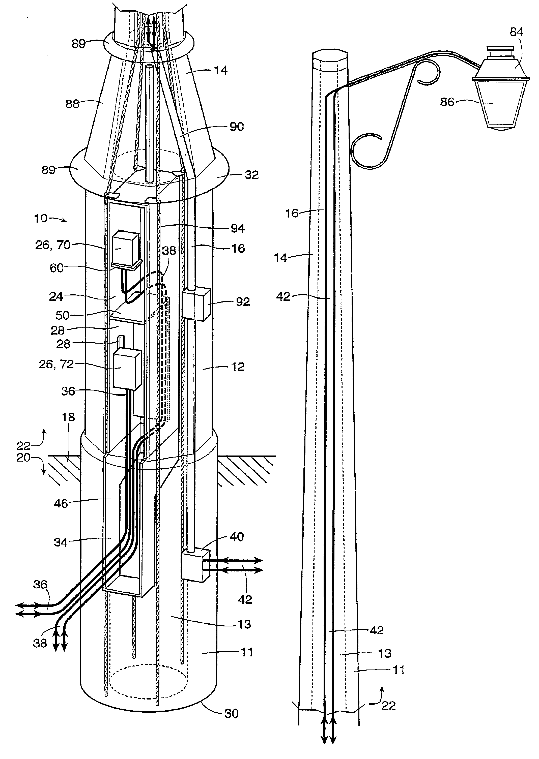
[0027]The multifunction utility pole of the present invention is shown in FIG. 1, with several elements shown in phantom and exploded view for clarity. The pole is generally indicated with reference numeral 10, and broadly comprises a base portion 12, a pole portion 14, and a wiring path 16. The pole has an outer wall 11 surrounding a hollow interior core 13. It can be seen that the utility pole 10 is installed in the ground 18, and accordingly includes a below-ground portion 20 and an above-ground portion 22.

[0028]For convenient representation, in order to show sufficient detail, the utility pole of the present invention is shown in two parts in FIG. 1, with the left-side drawing showing a lower part and the right-side drawing showing an upper part of the utility pole 10. For further reference, a view of the pole 10 as a whole is shown in FIG. 7. The multi-function utility pole of the present invention provides the traditional street lighting utility, and as discussed in greater de...


PUM


Abstract

A multifunction utility pole comprising a base portion suitable for installation in the ground or mounting on a surface, the base portion including a housing for a first utility, a pole portion extending above the base portion, the pole portion including a fixture for a second utility; and a wiring path extending through the base portion and the pole portion, to provide access for wiring to the second utility, wherein the utility pole is capable of simultaneously accommodating the first and second utilities.

Description

FIELD OF THE INVENTION[0001]This invention relates to the general field of distribution of utility services, and more particularly to utility poles.BACKGROUND OF THE INVENTION[0002]Communication services such as telephone, cable television, and Internet access are generally considered essential in personal and business life, and accordingly have become universally available in most homes, offices, and other locations in the community. These communication services generally involve one or two-way transmission of a communication signal between a central location, a number of sub-distribution points, and end users. In most cases the final connection between the last local distribution point and the end user is delivered through some sort of physical link such as a wire pair, co-axial cable, or fiber optic cable.[0003]In this arrangement, certain equipment is generally needed at the last local distribution point to serve a group of end users. In dense urban areas many locations are conv...

Claims


Application Information

Patent Timeline
Patent Type & Authority Patents(United States)
IPC IPC(8): E04C3/30F21S13/10E04H12/00E04H12/12
CPCE04H12/12E04H12/003
Inventor KUEBLER, ULRICHDEGASPERIS, ANTONIO
Owner CON CAST PIPE INC
Why Eureka
Try Eureka