
Pressure sensor

a technology of pressure sensor and sensor body, applied in the direction of fluid pressure measurement, fluid pressure measurement by electric/magnetic elements, instruments, etc., can solve the problems of sensor inability to meet the needs of the environment and non-negligible perturbations of the surrounding environmen

Inactive Publication Date: 2006-06-13
AGILENT TECH INC
View PDF10 Cites 7 Cited by
  • Summary
  • Abstract
  • Description
  • Claims
  • Application Information

AI Technical Summary

Benefits of technology

[0009]Advantageously, the technology for manufacturing MEMS exploits manufacturing methods similar to those used for integrated circuits, and thus it can benefit from similar levels of quality, reliability, sophistication and inexpensiveness typical of integrated circuits.
[0011]According to a preferred embodiment, the frequency and / or amplitude variations induce a measurable variation of a parameter of the electric circuit within which the micro-electro-mechanical vibrating device is connected, thereby allowing the pressure variations to be obtained from the behaviour of this variable electric parameter.

Problems solved by technology

Yet the known sensors are not suitable for applications in which miniaturising the sensor is necessary in order to measure the pressure in small-sized chambers or in situations where a non-miniaturised sensor could cause non-negligible perturbations on the surrounding environment.

Method used


Image

  • Pressure sensor
  • Pressure sensor
  • Pressure sensor

Examples


first embodiment

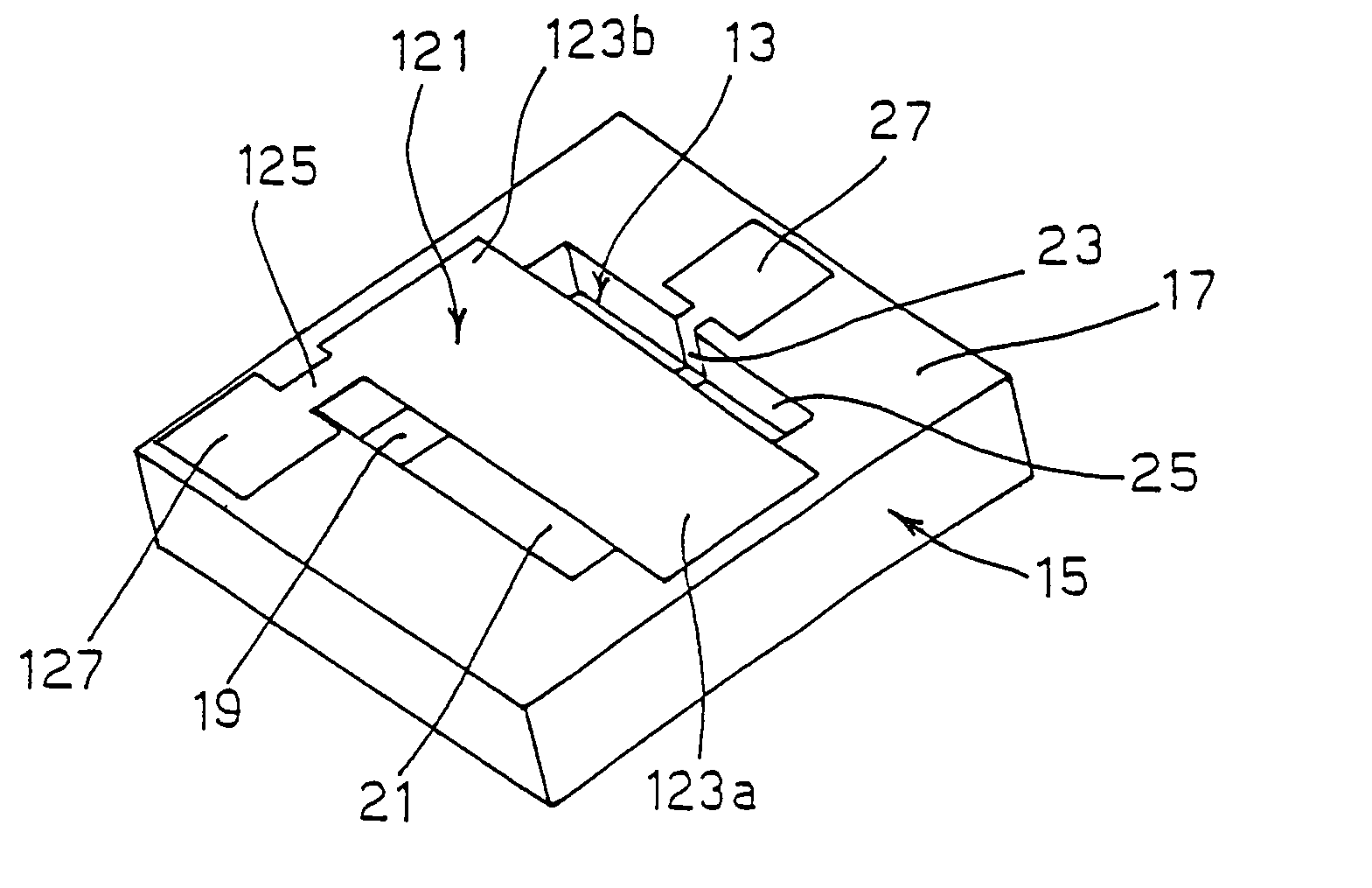
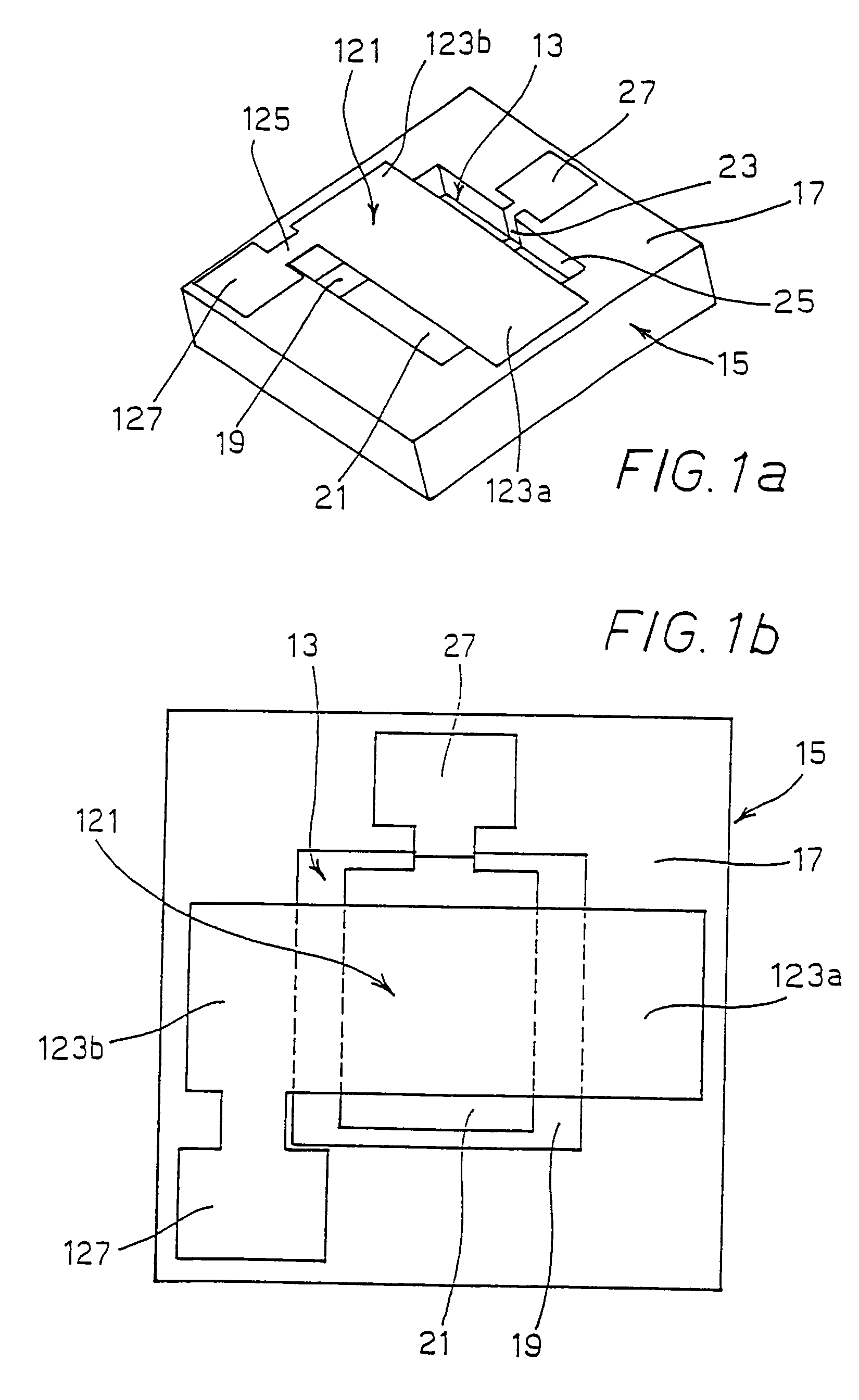
[0020]Referring to FIGS. 1a and 1b, there is shown the micro-electro-mechanical device of the pressure sensor according to the invention.

[0021]According to that embodiment, a vibrating planar resilient membrane 121 is suspended above a cavity 13 formed in a supporting base 15. The membrane 121 has a substantially rectangular shape and is fastened to peripheral rim 17 surrounding cavity 13 in supporting base 15 at two rectangular fastening regions 123a, 123b adjacent to the minor sides of membrane 121. The membrane is further provided with a side extension 125 partly overlapping peripheral rim 17 so as to define a corresponding contact area 127.

[0022]Supporting base 15 preferably is a silicon substrate or wafer on which cavity 13 has been formed by conventional etching techniques. A metal control electrode 21 is located inside cavity 13, in contact with bottom 19, and it is provided with a side extension 23 bent against side wall 25 of cavity 13. That extension partly covers peripher...

second embodiment

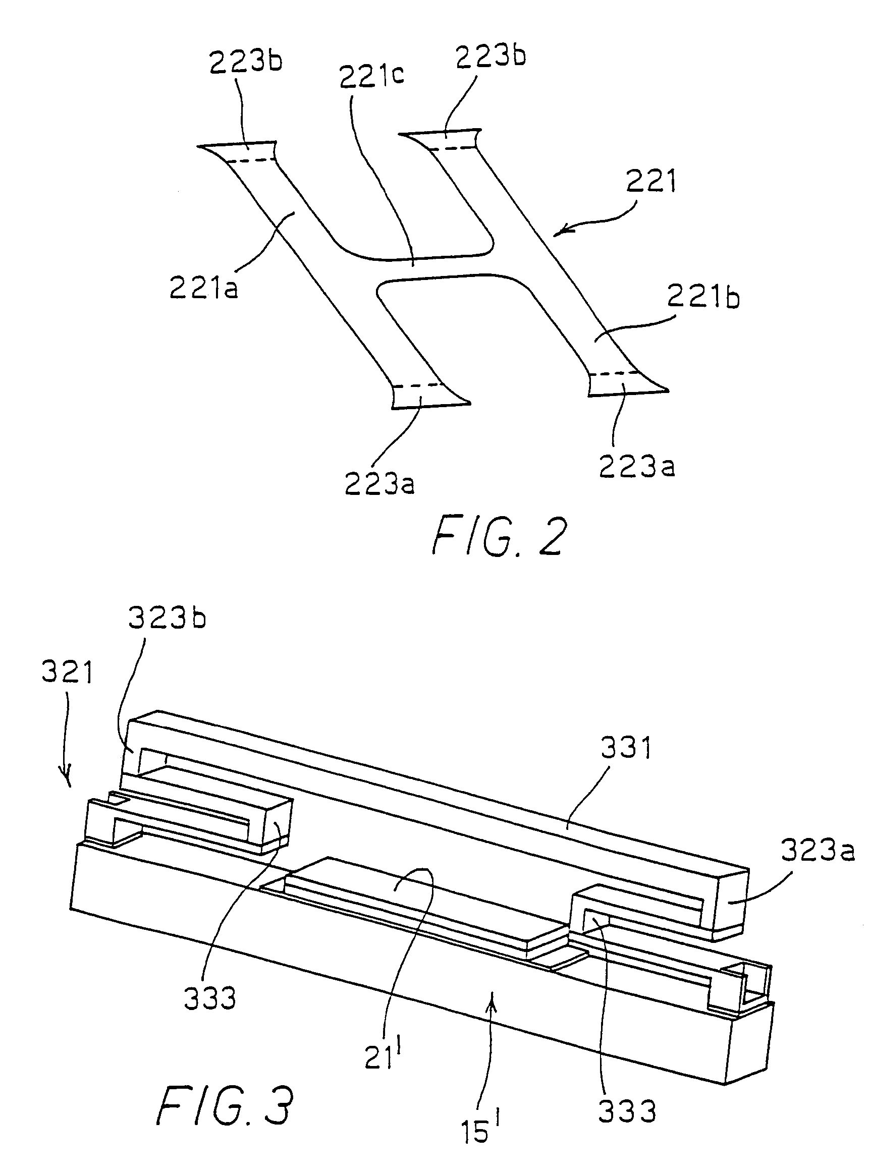
[0032]Referring to FIG. 2, where elements identical to those shown in FIGS. 1a and 1b have been omitted, the invention is shown in which the vibrating pumping stage is obtained by means of a planar, substantially H-shaped resilient membrane 221 comprising two parallel longitudinal beams 221a, 221b and a transversal central beam 221c. Similarly to the embodiment shown in FIGS. 1a and 1b, both parallel beams 221a, 221b are fastened at their respective ends 223a, 223b to peripheral rim 17 of supporting base 15. H-shaped membrane 221 is thus suspended above cavity 13 formed in supporting base 15.

[0033]Due to such a configuration, the H-shaped membrane may be imparted a torsional oscillation allowing attaining high resonance frequencies and great amplitudes. Actually, torsional resonance frequency is much higher than the flexion one. For instance, an aluminium membrane 150 μm long, 15 μm wide and 1.5 μm thick will have the following resonance frequencies: flexion 3.5e5 Hz, torsion 2.0e6 ...

third embodiment

[0035]Turning now to FIG. 3, the invention is shown in which a multilayer vibrating assembly 321 is provided.

[0036]According to this embodiment, assembly 321 comprises a substantially rigid membrane 331 supported by substantially S-shaped resilient members or suspension springs 333, located under membrane 331 at respective opposed ends 323a, 323b thereof.

[0037]Resilient members 323a, 323b will be in turn fastened to a rectilinear supporting base 15′ onto which a control electrode 21′ is provided, in order to make assembly 321 vibrate due to the application of an electric field between said electrode 21′ and membrane 331.


PUM

PropertyMeasurementUnit
sizeaaaaaaaaaa
thicknessaaaaaaaaaa
thicknessaaaaaaaaaa

Abstract

A pressure sensor is a micro-electro-mechanical vibrating device, with a silicon substrate (15; 15′) onto which a single-layer or multilayer vibrating assembly (121; 221; 321) is formed. It comprises an electrode (21; 21′), which makes the assembly to oscillate relative to the substrate at the resonance frequency or at another known frequency, and a detector for detecting the actual frequency and / or amplitude of said oscillation. The actual frequency and / or amplitude are affected by the conditions, in particular the pressure, of the external environment and the variations of the frequency and amplitude with respect to the values set by the electrode is used to measure pressure variations in the surrounding environment.

Description

FIELD OF THE INVENTION[0001]The present invention relates to a pressure sensor.[0002]More particularly, the present invention concerns a pressure sensor comprising a vibrating member, of which the oscillation frequency and amplitude are affected by the pressure conditions of the external environment and can therefore be exploited to measure pressure variations in the surrounding environment.BACKGROUND OF THE INVENTION[0003]Pressure sensors, or sensors of other physical quantities such as temperature, density and so on, employing a vibrating member are already known. These sensors exploit the influence of the pressure, temperature and / or density conditions of the surrounding environment on the oscillation frequency and amplitude of the vibrating member, and obtain the variations of the physical quantity of interest from the measurement of the oscillation frequency and amplitude deviations from the expected values.[0004]Sensors of the above kind are disclosed for instance in U.S. Pat....

Claims


Application Information

Patent Timeline
Patent Type & Authority Patents(United States)
IPC IPC(8): G01L9/00G01L21/22G01P3/00H01L29/84
CPCG01L9/0016G01L21/22G01L9/0019
Inventor CORREALE, RAFFAELEMACCARRONE, CRISTIANBUSSO, MARIO
Owner AGILENT TECH INC
Learn More