
Frame-based bladder apparatus for seat occupant weight estimation

a bladder and seat technology, applied in the direction of pedestrian/occupant safety arrangements, instruments, tractors, etc., can solve the problems of seat cushion and spring downward deflection, frame-based weight estimation is subject to significant errors, etc., and achieve the effect of preventing shunting of occupant weigh

Inactive Publication Date: 2006-06-13
DELPHI TECH INC
View PDF24 Cites 12 Cited by
  • Summary
  • Abstract
  • Description
  • Claims
  • Application Information

AI Technical Summary

Benefits of technology

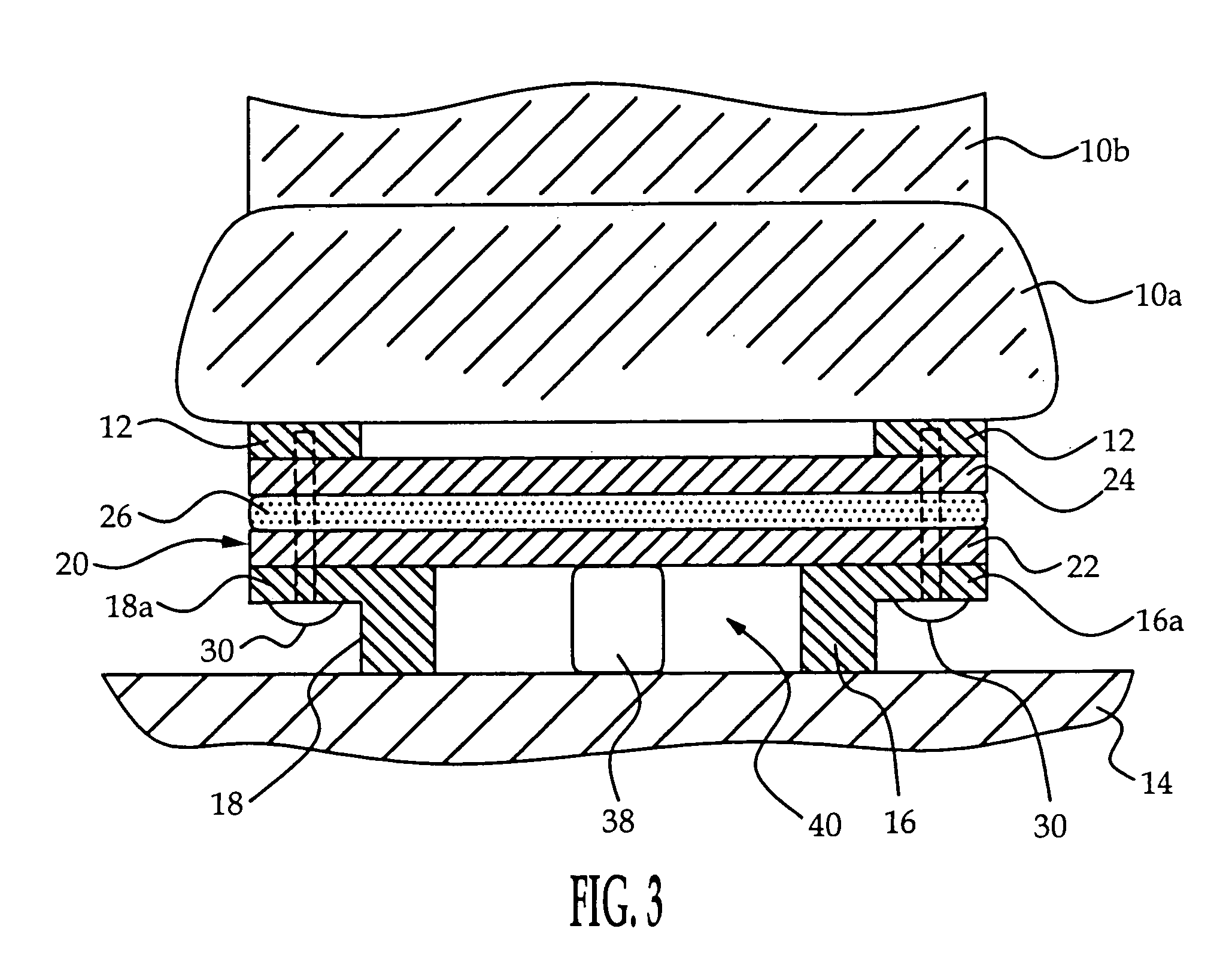
[0005]The present invention is directed to an improved frame-based occupant weight estimation apparatus for a vehicle seat that is supported by two or more brackets secured to the vehicle floor, where the weight estimation apparatus includes a load-cell that spans an open space between the floor brackets to prevent shunting of the occupant weight through a foreign object lying on the floor between the floor brackets. The load cell includes a fluid filled bladder sandwiched between first and second rigid plates, and is held in place between the seat frame and the floor brackets by a set of fasteners. A spring preloads the bladder so that deviations of the bladder fluid pressure from the preload pressure will be indicative of occupant weight. The first plate spans the open space between the floor brackets so that the fluid pressure is indicative of occupant weight even in cases where a portion of the occupant weight is supported by a foreign object lying on the floor between the floor brackets.

Problems solved by technology

However, frame-based weight estimation is subject to significant error in cases where a foreign object such as a beverage container is placed on the floor under the seat and the undercarriage of the seat comes into contact with the object when occupant weight causes downward deflection of the seat cushion and springs.

Method used


Image

  • Frame-based bladder apparatus for seat occupant weight estimation
  • Frame-based bladder apparatus for seat occupant weight estimation
  • Frame-based bladder apparatus for seat occupant weight estimation

Examples


Embodiment Construction

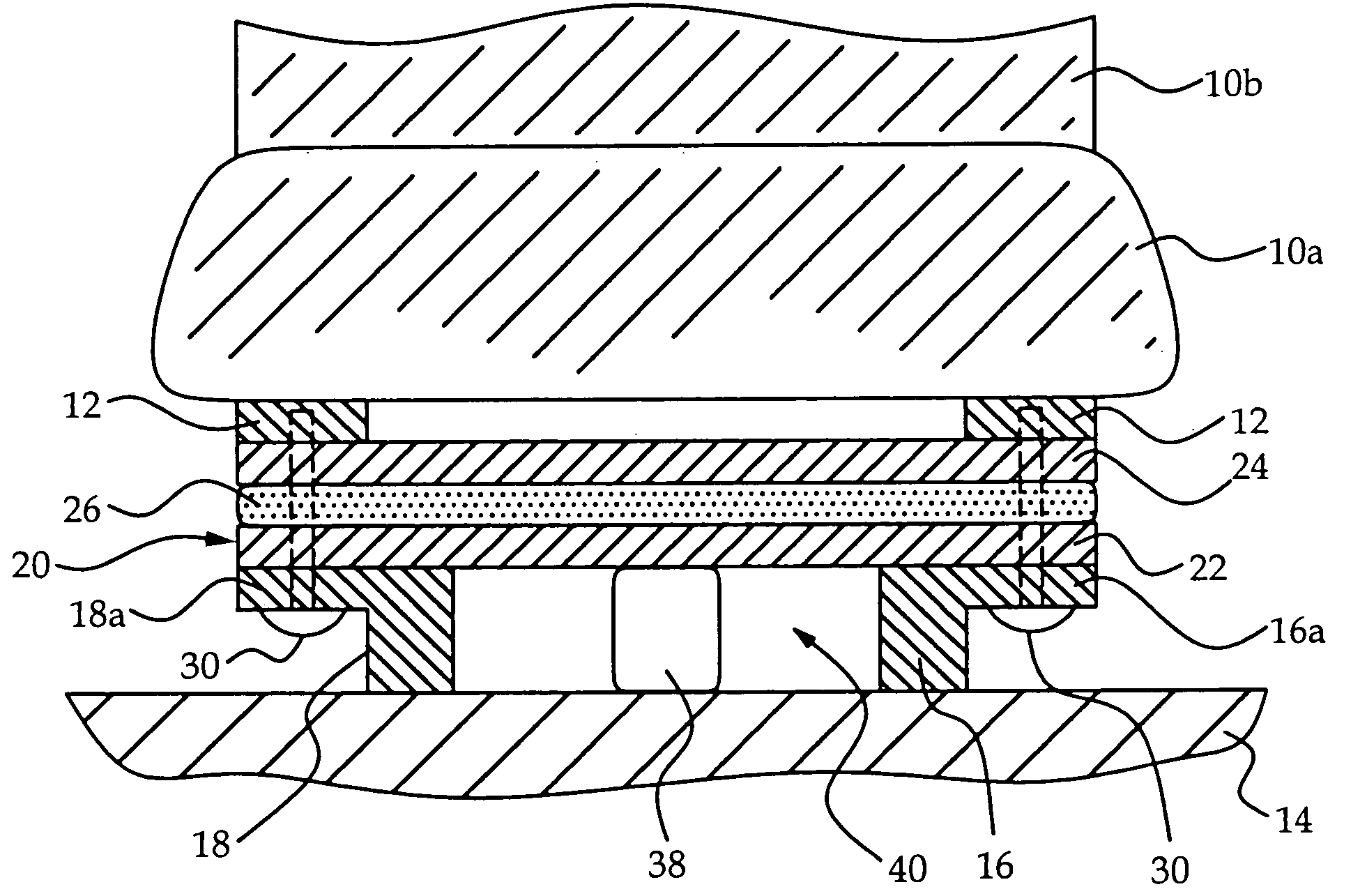
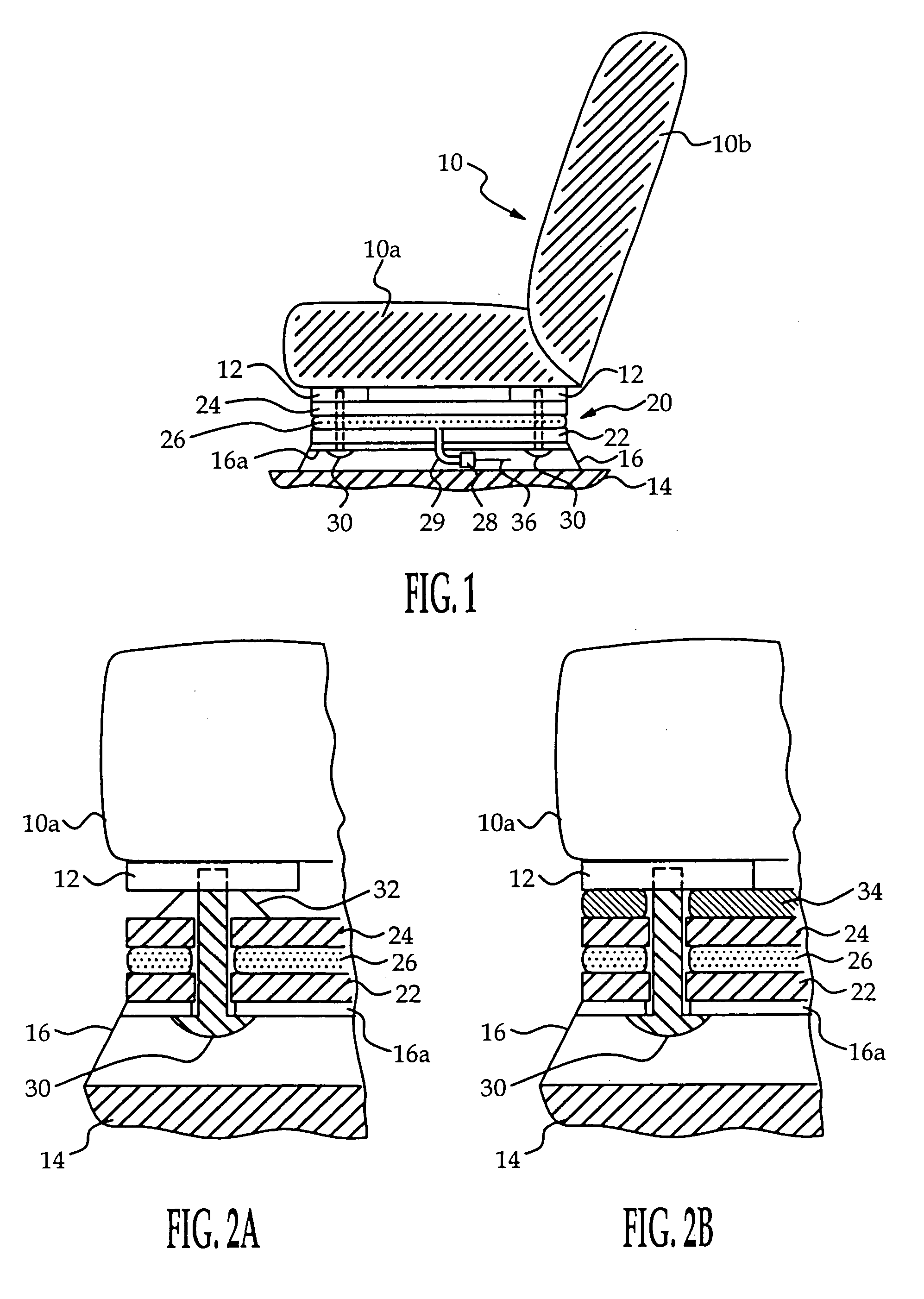
[0010]Referring to the drawings, and particularly to FIG. 1, the reference numeral 10 generally designates a vehicle seat, including seat and backrest cushions 10a, 10b supported on a frame including a set of mounting pads 12. In the illustrated embodiment, there are four mounting pads: left front, right front, left rear and right rear, each designated by the reference numeral 12. The seat 10 is secured to the vehicle floor 14 by a pair of laterally spaced floor brackets 16, 18 that are bolted to floor 14, and a load cell 20 is interposed between the seat frame mounting pads 12 and the floor brackets 16, 18 for estimating the weight of a seat occupant.

[0011]The load cell 20 includes first and second rigid plates 22 and 24, a fluid-filled elastomeric bladder 26 interposed between the plates 22 and 24, and a pressure sensor 28 coupled to a bladder exit port 29 for detecting the fluid pressure within bladder 26. In the illustrated embodiment, the floor brackets 16, 18 include integral ...


PUM


Abstract

A frame-based occupant weight estimation apparatus for a vehicle seat that is supported by two or more floor brackets secured to the vehicle floor spans an open space between the floor brackets to prevent shunting of the occupant weight through a foreign object lying on the floor between the floor brackets. The weight estimation apparatus includes a fluid filled bladder sandwiched between first and second rigid plates, and is held in place between the seat frame and the floor brackets by a set of fasteners. A spring preloads the bladder so that deviations of the bladder fluid pressure from the preload pressure will be indicative of occupant weight. The first plate spans the open space between the floor brackets so that the fluid pressure is indicative of occupant weight even in cases where a portion of the occupant weight is supported by a foreign object disposed between the floor brackets.

Description

TECHNICAL FIELD[0001]This invention is directed to apparatus for detecting the weight of an occupant of a motor vehicle seat for purposes of determining whether and how forcefully to deploy supplemental restraints, and more particularly to apparatus for measuring forces applied to a frame of the vehicle seat.BACKGROUND OF THE INVENTION[0002]Vehicle occupant detection systems are useful in connection with air bags and other pyrotechnically deployed restraints as a means of judging whether, and how forcefully, to deploy the restraint. One fundamental parameter in this regard is the weight of the occupant, as weight may be used as a criterion to distinguish between an adult and an infant or small child.[0003]Most prior weight estimation techniques involve installing a pressure sensitive element such as a variable resistance pad or a fluid filled bladder in or under a vehicle seat cushion, and utilizing the pressure measurement as an indication of occupant weight. See, for example, the ...

Claims


Application Information

Patent Timeline
IPC IPC(8): B60K28/04G01G5/04B60N2/00B60R21/01B60R21/015G01G19/414
CPCB60N2/002B60R21/01516G01G19/4142B60N2/0025B60N2210/44B60N2/0031
Inventor MURPHY, MORGAN D.TIEMAN, CRAIG AFORTUNE, DUANE D.MCKINLEY, JAMES R.
Owner DELPHI TECH INC
Learn More