Sling for a shoulder weapon

Inactive Publication Date: 2006-06-13
JOHNSON DAVID A
View PDF9 Cites 34 Cited by
  • Summary
  • Abstract
  • Description
  • Claims
  • Application Information

AI Technical Summary

Benefits of technology

[0008]The present invention overcomes the aforementioned shortcomings of previously available slings for military shoulder weapons by providing a sling of which a portion is in the form of a strap extending through a strap slide aperture and then doubling back along its own length for at least some distance to a position where its traveling end is held releasably by engagement of a quick release plate with an engagement member attached to a main portion of the strap. The quick release plate is normally held generally parallel with the main portion of the strap by tension in the sling. Reorientation of the quick release plate to a position generally perpendicular to the main portion of the sling allows a part of the engagement member to flex and thus release the quick release plate from the engagement member, allowing the quick release plate to slide along the sling strap toward the strap slide aperture and allowing the doubled portion of the sling strap to move through and then away from the slide aperture, thus increasing the effective length of the sling.

Problems solved by technology

Depending on the locality of a target with respect to a structure behind which a soldier can be partially concealed, however, in some cases it is necessary for a soldier to shoot with the weapon at his opposite, non-preferred shoulder.
In such slings the first strap, extending closely alongside the weapon, can interfere with operation of the weapon, and the second strap portion of the sling, when released to slide along the inner strap, extends more closely around the body of the soldier, increasing the difficulty of removing the weapon quickly should that be required.
Previously available devices for releasing and reengaging the sliding end of the second strap have been less than desirably easy to operate, particularly for a soldier wearing gloves.
Arrangements for attaching the rear end of a sling to a rifle buttstock at a location separated from an installed sling swivel have been cumbersome and complicated.
The doubled loop of strapping must be pulled forward from the slide to release the movable front end to slide along the inner sling strap, but this requires a significant pull toward the front end of the weapon, causing a slight delay before the sliding front end of the sling can be moved rearwardly along the inner sling strap.

Method used


Image

  • Sling for a shoulder weapon
  • Sling for a shoulder weapon
  • Sling for a shoulder weapon

Examples


Embodiment Construction

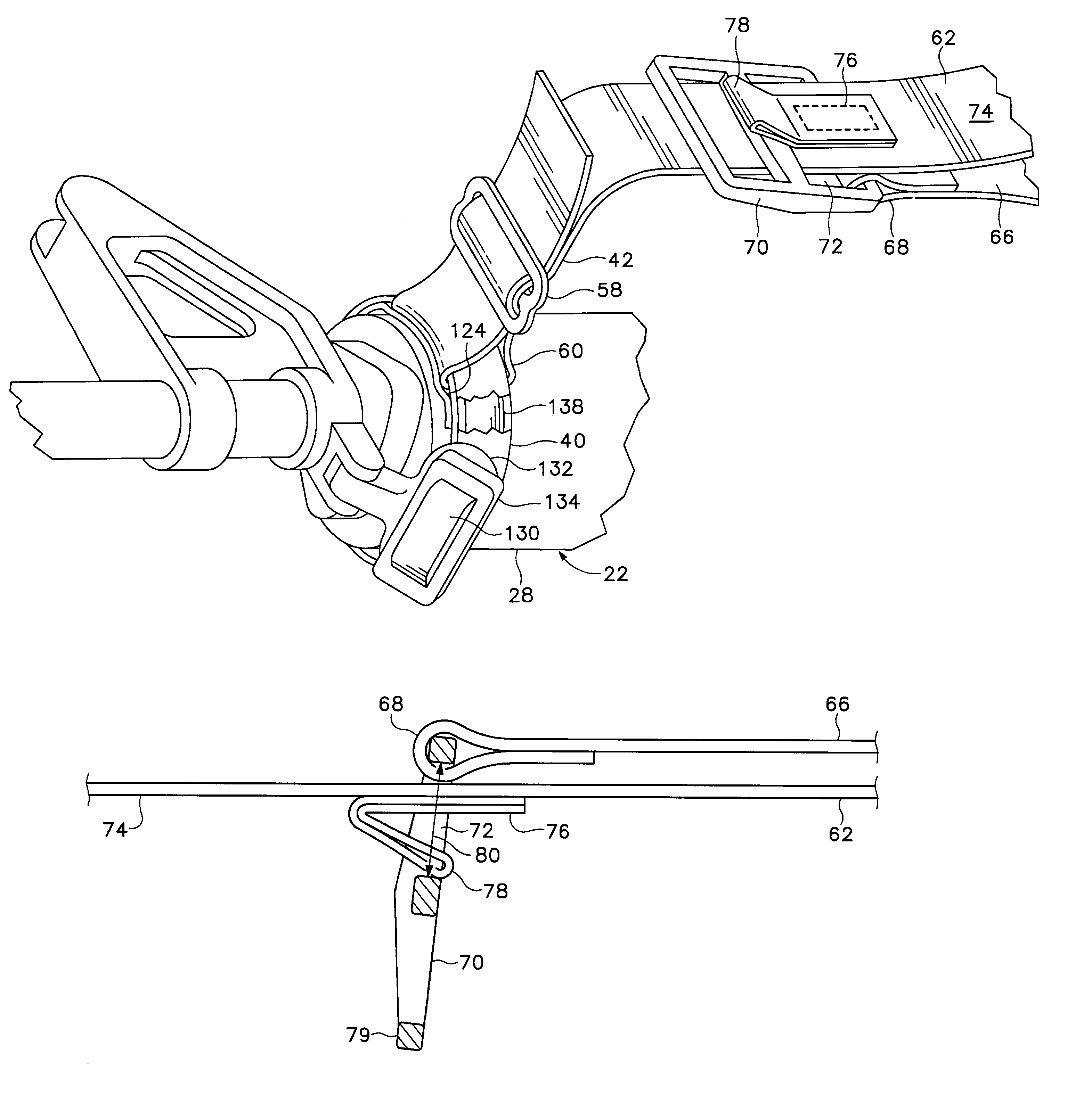
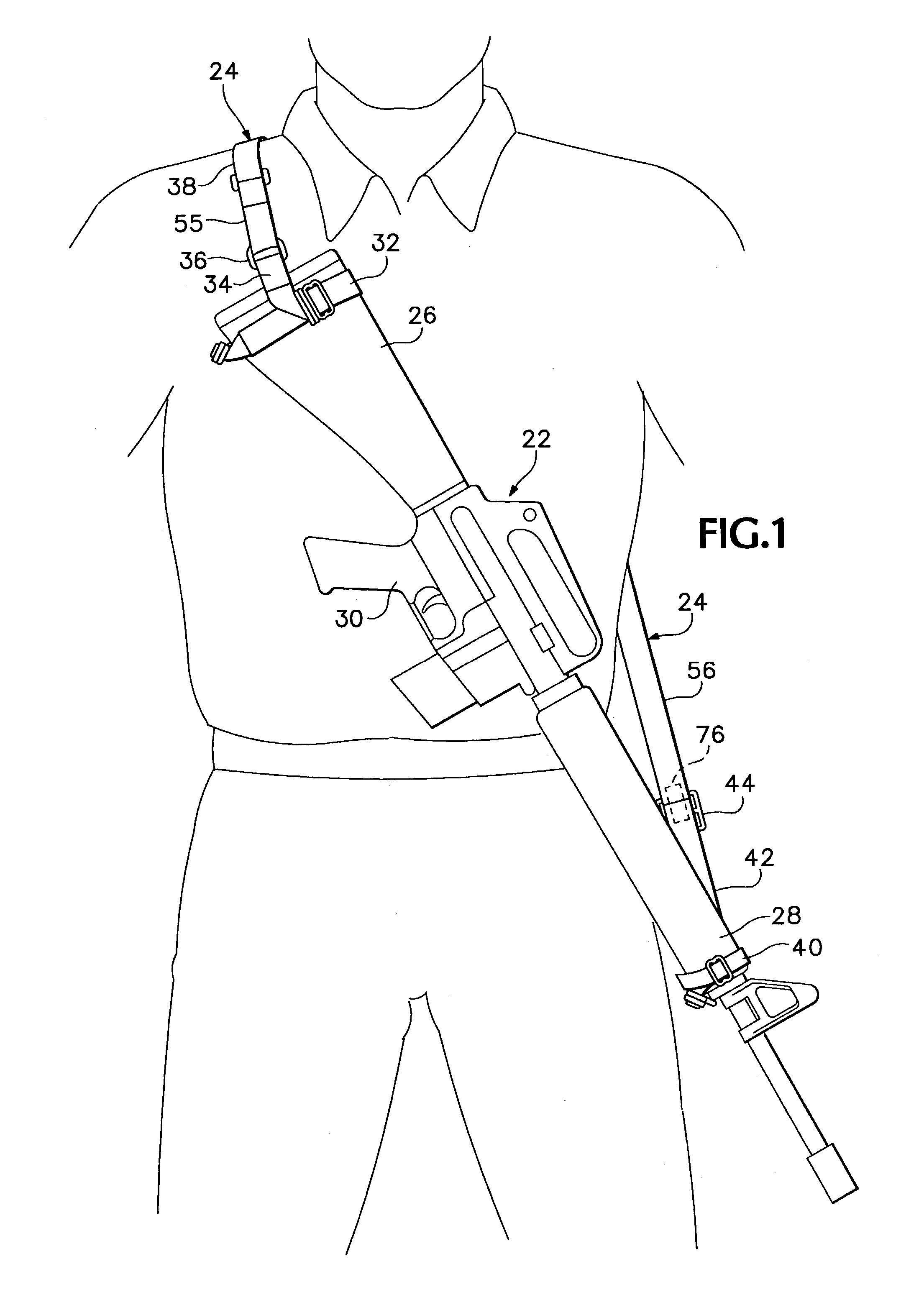
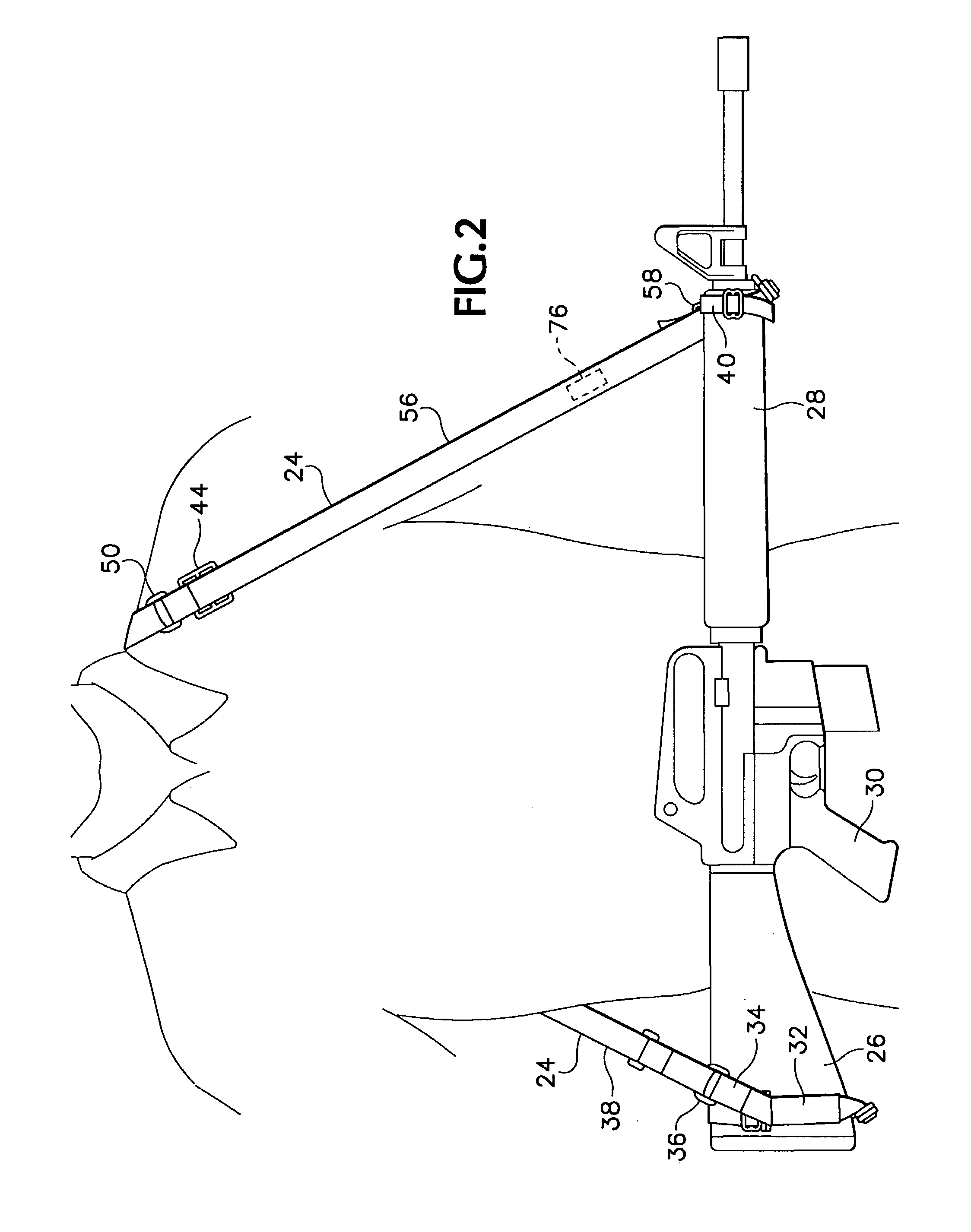
[0032]Referring now to the drawings which form a part of the disclosure herein, in FIG. 1 a military shoulder weapon, in this case an automatic rifle 22, is carried by a soldier, supported by a sling 24 attached to the automatic rifle 22 and arranged to extend from the buttstock 26 over the soldier's right shoulder, around his back, and to the forestock 28, supporting the automatic rifle 22 in a high carry position which enables a right-handed soldier to raise the automatic rifle 22 quickly to his right shoulder and there to grip the pistol grip 30 with his right hand and support the forestock 28 with his left hand. A person using such a sling can thus raise the automatic rifle 22 quickly to his preferred shoulder in the usual shooting position while the sling 24 remains in its normal configuration arranged to support the automatic rifle 22 in the high carry position. A buttstock sling mounting loop assembly 32 includes a short attachment strap 34 to which a D-ring 36 is fastened to...


PUM


Abstract

A sling for a shoulder weapon, such as a military assault rifle or carbine, in which the effective length of the sling can be extended quickly and quietly and then easily and quietly retracted to the original length. A quick release plate and an engagement member cooperate to hold a loop of strap material to provide the shorter configuration of the sling, and the quick release plate can pass over the engagement member to lengthen the sling when the quick release plate is turned to a position perpendicular to the length of the sling. The opposite ends of the sling can be attached to a weapon using secure, quiet fittings.

Description

BACKGROUND OF THE INVENTION[0001]The present invention relates to slings for shoulder weapons, and particularly for military tactical weapons.[0002]It is usually desirable to use a sling to carry a military shoulder weapon so it is quickly available and ready for use while leaving a soldier's hands free for performing other tasks when the weapon is not actually in use.[0003]Many military rifle slings have been known in the past, and some of them have been designed to be lengthened readily from a length best adapted for carrying the weapon to a length best for using the weapon while in a particular position. Usually, a sling permits a weapon to be raised to a soldier's preferred shoulder. Depending on the locality of a target with respect to a structure behind which a soldier can be partially concealed, however, in some cases it is necessary for a soldier to shoot with the weapon at his opposite, non-preferred shoulder. Preferably, the soldier should be able to move the weapon to the...

Claims


Application Information

Patent Timeline
IPC IPC(8): F41C23/02F41C33/00
CPCF41C33/002Y10S224/913
Inventor JOHNSON, DAVID A.
Owner JOHNSON DAVID A
Why Eureka
Try Eureka