Surgical stapling device

a stapling device and surgical technology, applied in the field of health care devices, can solve the problems of inability to afford current available surgical staple devices and supplies, inability to take advantage of stapling technology, and high cost of surgical staple devices, so as to prevent damage to the staple former

Inactive Publication Date: 2006-06-13
THOMASSON DENNIS M
View PDF68 Cites 68 Cited by
  • Summary
  • Abstract
  • Description
  • Claims
  • Application Information

AI Technical Summary

Benefits of technology

[0018]The surgical staple cartridge includes a housing member having a staple-forming end, a plurality of staples having a lead staple movably positioned in the housing member and a first opening in the staple-forming end of the housing member to allow access to the lead staple and a second opening in the staple-forming end of the housing member to allow the lead staple to move therethrough. The staple cartridge preferably contains a feeder shoe for urging the plurality of staples toward the staple-forming end of the housing member. To prevent staple jamming, the staple cartridge also preferably contains a fixed blocking surface on the housing member and a traveling blocking surface on the feeder shoe. The traveling blocking surface is sized so that the feeder shoe moves along the fixed blocking surface of the housing member while blocking the staple. The staple cartridge also preferably includes a flexible arm extending from the housing member and moving between a memory position and a flexed position outwardly from the memory position for a snap fit of the staple cartridge to the stapling device. Additionally, the feeder shoe is angled to prevent damage to the staple former and feeder shoe when the trigger member is squeezed when no staples remain in the staple cartridge.

Problems solved by technology

However, not all clinicians are able to take advantage of stapling technology because available surgical stapling devices are expensive.
For example, clinicians who work in low-income regions or without insurance support, are often unable to afford currently available surgical staple devices and supplies.
While advantageous in the respects discussed, current surgical stapling devices present certain limitations.
Such stapling devices are not economically advantageous in the long run.
However, if premium quality components are used, disposing of these parts each time the staples are used raises the cost of using the stapling device.
However, current surgical stapling devices employing a replaceable cartridge do not allow for reuse of both a staple former and an anvil.
A limitation in such feeder shoes and urging mechanisms is that staples are allowed to jam on the sliding surface as the staples move toward the staple-forming or exiting end of the stapling device.
Such staple jams can be at least inconvenient to clinicians who temporarily cannot utilize the stapling device.
A limitation in the feeder shoes and urging mechanisms which can lead to staple jams is that while all such feeder shoes contact at least a part of one of the staples, and some feeder shoes contact much of one side of a staple, when a staple slips, the staple can be lodged in spaces either between the staple stack containing a plurality of staples and the track upon which the plurality of staples slide, within other spaces existing within the feeder shoe itself, or between the feeder shoe and the track upon which the staple stack slides.
Another limitation of current feeder shoes is that if such feeder shoes are extended completely to the end of the staple cartridge, as when all staples in the staple cartridge have been used so that no staples remain in the staple cartridge, forcing the staple former on the feeder shoe can damage these parts.
Finally, a limitation of current surgical stapling devices is that staples are implanted substantially orthogonal to the skin surface.

Method used


Image

  • Surgical stapling device
  • Surgical stapling device
  • Surgical stapling device

Examples


Embodiment Construction

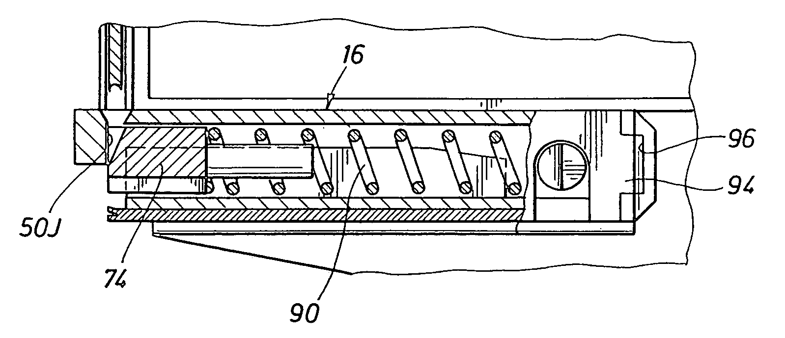
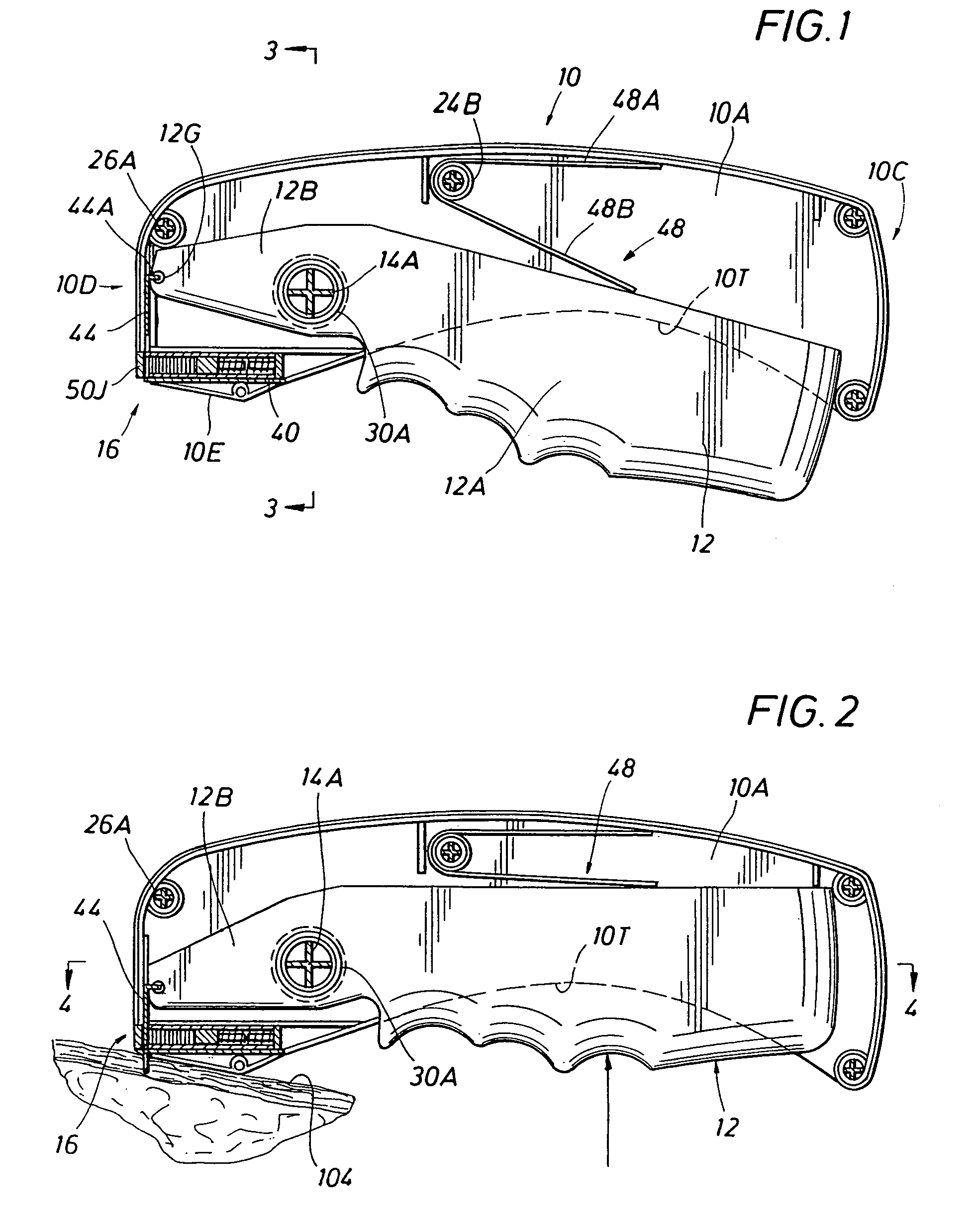
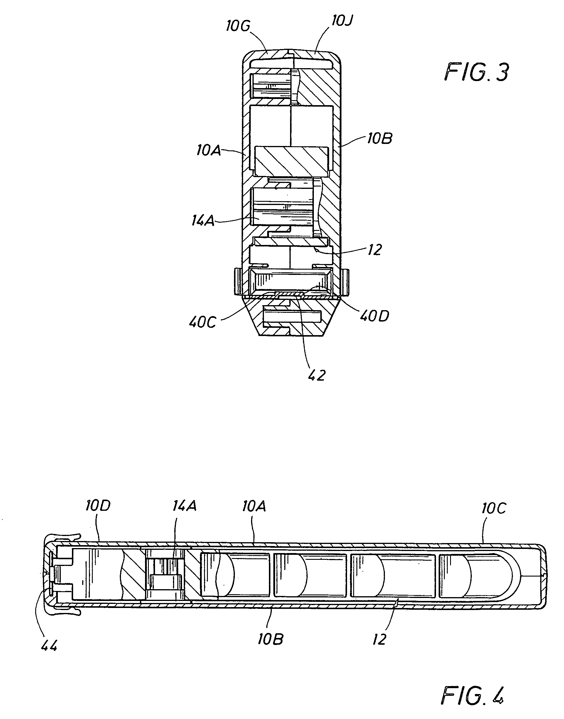
[0042]As shown in FIG. 1, the surgical stapling device of the present invention comprises a body member, generally indicated as 10, and a trigger member 12 movably positioned with the body member 10. As best shown in FIG. 5, the trigger member 12 is pivotally movable about a trigger pivot opening 12C. Preferably, the body member 10 comprises a right body member half 10A and a left body member half 10B. The body halves are assembled in mated relationship, as best shown in FIG. 5. Also as shown in FIG. 5, the trigger pivot opening 12C is received about right trigger pivot male member 14A and a left trigger pivot female member 14B that are interengaged in a mated relationship. As best shown in FIG. 4, the body member 10 has a rearward portion 10C constituting a handle portion and a forward portion 10D. As best shown in FIGS. 6 and 7, a staple cartridge 16 is located within a staple cartridge recess 18 in the forward portion 10D. Returning to FIG. 1, the rearward or handle portion 10C o...


PUM

PropertyMeasurementUnit
insertion angleaaaaaaaaaa
insertion anglesaaaaaaaaaa

Abstract

A surgical stapling device having a removable staple cartridge is disclosed. The cartridge includes a first opening in the staple-forming end of the housing member to allow access to the a staple and an aligned second opening to allow the lead staple to move therethrough. The staple cartridge also comprises a fixed blocking surface on the housing member and a traveling blocking surface on a feeder shoe. The traveling blocking surface is sized so that the feeder shoe moves relative to the fixed blocking surface while moving the staple. The feeder shoe is further shaped so that, when the trigger member is actuated when no staples remain in the staple cartridge, the staple former is not blocked by the feeder shoe.

Description

CROSS-REFERENCE TO RELATED APPLICATIONS[0001]This application is a continuation-in-part of U.S. application Ser. No. 10 / 156,716 filed on May 28, 2002, now abandoned which is hereby incorporated by reference in its entirety for all purposes.STATEMENTS REGARDING FEDERALLY SPONSORED RESEARCH OR DEVELOPMENT[0002]Not ApplicableREFERENCE TO A MICROFICHE APPENDIX[0003]Not ApplicableBACKGROUND OF THE INVENTION[0004]1. Field of the Invention[0005]The present invention relates to health care devices comprising medical and veterinary devices, and more particularly to devices useful in suturing or closing wounds or incisions.[0006]2. Description of the Related Art[0007]The use of surgical staples in the health care field, comprising both the medical and veterinary fields, to close wounds and incisions has begun to, in many contexts, replace conventional suture ligature.[0008]Surgical skin stapling has been found to be desirable in that it requires less skill of the health care clinician than co...

Claims


Application Information

Patent Timeline
Patent Type & Authority Patents(United States)
IPC IPC(8): A61B17/068
CPCA61B17/0684A61B2017/0688
Inventor BROWN, PHILLIP CLAY
Owner THOMASSON DENNIS M
Why Eureka
Try Eureka