Lamp module for planar source device

a technology of lamp modules and planar sources, applied in the field of illumination systems, can solve the problems of less convenient use of lamp modules, less convenient use of lamp holders, and generally expensive scanners, and achieve the effect of shortening the lamp and reducing the overall weight of the lamp holders

Inactive Publication Date: 2006-06-13
INTELLECTUAL VENTURES I LLC
View PDF2 Cites 0 Cited by
  • Summary
  • Abstract
  • Description
  • Claims
  • Application Information

AI Technical Summary

Benefits of technology

[0009]Accordingly, one object of the present invention is to provide a lamp module can be used, for example, for a scanner that can use a shorter lamp inside a lamp holder. The lamp holder has a curved arc surface capa

Problems solved by technology

However, these scanners are generally expensive and uncommon.
Due to a larger volume of occupation, the lamp holder 124 is less convenient to use.
This type of lamp module has some di

Method used


Image

  • Lamp module for planar source device
  • Lamp module for planar source device
  • Lamp module for planar source device

Examples


Embodiment Construction

[0021]Reference will now be made in detail to the present preferred embodiments of the invention, examples of which are illustrated in the accompanying drawings. Wherever possible, the same reference numbers are used in the drawings and the description to refer to the same or like parts.

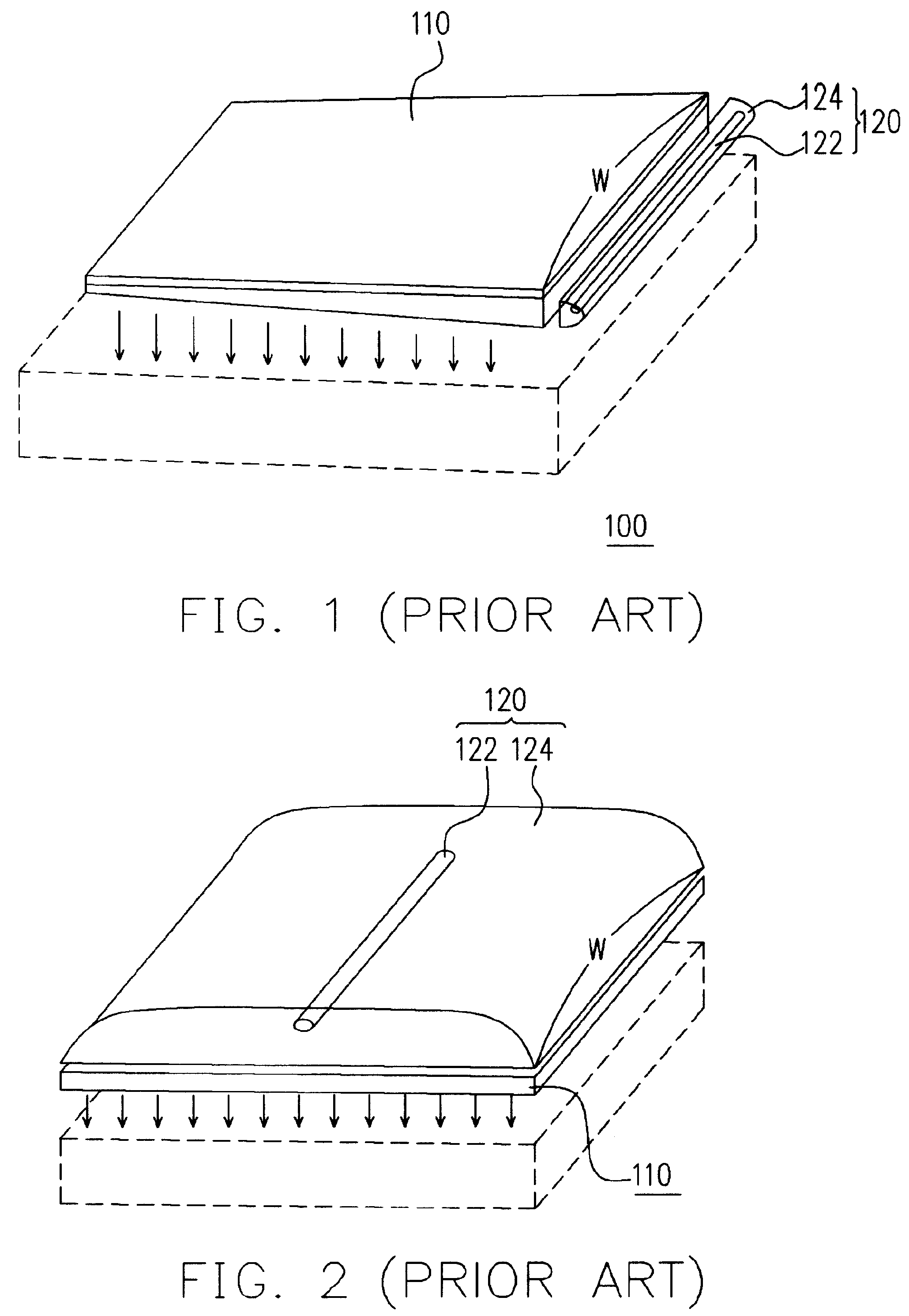
[0022]Because a light-guiding plate is an ideal device for producing uniform light intensity across an area, light-guiding plates are adopted in most large area developing and illumination systems to produce a planar light source. The following is a more detailed description of the function of the light-guiding plate.

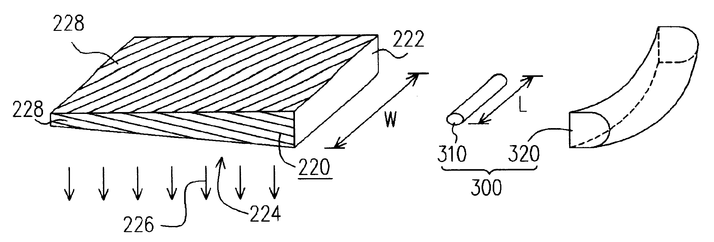
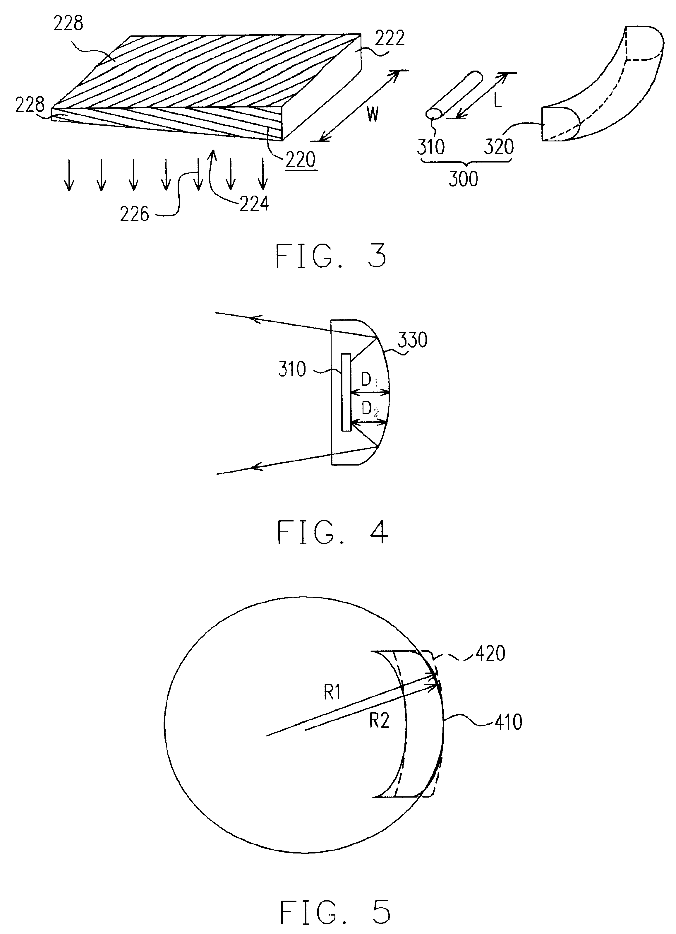
[0023]FIG. 3 is a perspective view of all the disembodied components constituting a planar light source device according to one preferred embodiment of this invention. As shown in FIG. 3, the light-guiding plate 220 has a light-inlet surface 222 and a light-emitting surface 224. The light-inlet surface 222 mainly receives incoming light. The light-emitting surface 224 is, for example, a ...


PUM


Abstract

A lamp module comprising a lamp holder and a lamp is provided. The lamp holder has a structure with a curved arc surface such that the ends of the structure are inwardly converging. Light from the lamp impinging upon the curved arc surface is scattered out to a linear dimension greater than the original length of the lamp. The scattered light is projected onto the light-inlet surface of a light-guiding plate so that light emerges from the light-emitting surface as a planar light source.

Description

CROSS REFERENCE TO RELATED APPLICATIONS[0001]This application claims the priority benefit of Taiwan application serial no. 91220543, filed Dec. 18, 2002.BACKGROUND OF INVENTION[0002]1. Field of Invention[0003]The present invention relates to an illumination system. More particularly, the present invention relates to the lamp holder of a lamp module that has a shorter lamp and a specified curvature radius.[0004]2. Description of Related Art[0005]Due to a rapid increase in processing speed and data storage capacity of computers, processing efficiency of graphic images has improved considerably. Image processing equipment such as optical scanners has an ever-increasing resolution and scanning speed. Flatbed scanner is one of the most common types of scanners in the market. A flatbed scanner has a scanning platform such as a transparent glass panel for putting a scan document or a pattern. To capture the image on the scan document or pattern, an optical scanning module underneath the gl...

Claims


Application Information

Patent Timeline
IPC IPC(8): F21V7/04F21V7/00F21V7/09F21V8/00G02B6/00H04N1/028
CPCF21V7/005F21V7/09H04N1/0287H04N1/02815H04N1/0285H04N1/02855G02B6/0031F21Y2103/00F21Y2105/00G02B6/0055
Inventor TSENG, JEN-SHOUHUANG, YIN-CHUN
Owner INTELLECTUAL VENTURES I LLC
Why Eureka
Try Eureka