Hydrodynamic bearing, spindle motor using the same and disc drive apparatus provided with spindle motor

a technology of hydraulic bearing and disc drive, which is applied in the direction of sliding contact bearings, instruments, and recording information storage, etc., can solve the problems of reducing bearing rigidity, deteriorating the reliability of the disc drive apparatus, and reading and writing errors in recording data, so as to improve durability and reliability, reinforce the resistance property, and strengthen the seal strength of the second capillary seal portion

Active Publication Date: 2006-06-13
NIDEC CORP
View PDF12 Cites 12 Cited by
  • Summary
  • Abstract
  • Description
  • Claims
  • Application Information

AI Technical Summary

Benefits of technology

[0017]An object of the present invention is to maintain a seal strength of a capillary seal portion high even when a spindle motor is rotated at a high speed, to increase a volumetric capacity within the capillary seal portion, and to allow a sufficient amount of lubricating oil to be retained.
[0018]Further, another object of the present invention is to reinforce a resistance property against an external shock at a time when the spindle motor stops rotating.
[0019]Further, the other object of the present invention is to prevent the lubricating oil from being scattered to an external portion of the bearing with respect to the external shock at a time when the spindle motor stops rotating.
[0020]Further, the other object of the present invention is to provide a hydrodynamic bearing, a spindle motor and a disc drive apparatus which achieve the objects mentioned above and are excellent in a reliability and a durability.
[0022]In accordance with the aspect of the hydrodynamic bearing on the basis of the present invention, since it is possible to simultaneously achieve an expansion of a volumetric capacity of the capillary seal portion and a reinforcement of a resistance property against the external shock, it is possible to prevent the lubricating oil from being scattered to the external portion of the bearing portion even at a time when the spindle motor is rotated at a high speed. Further, since the second capillary seal portion is expanded progressively toward the outer side in the axial direction, the lubricating oil retained in the second capillary seal portion at a time when the spindle motor is rotated at the high speed is pressed to the side of the first capillary seal portion on the basis of the centrifugal force, whereby it is possible to reinforce a seal strength of the second capillary seal portion. Further, since the second capillary seal portion is expanded progressively toward the outer side in the axial direction, it is possible to reinforce the resistance property against the external shock from the axial direction at a time when the spindle motor stops rotating, and it is possible to prevent the lubricating oil from being scattered to the external portion of the bearing portion, so that an application range of the hydrodynamic bearing is expanded, it is possible to prevent the lubricating oil from coming short of the retaining amount within the bearing portion, and it is possible to improve a durability and a reliability.

Problems solved by technology

For example, in the case that the scattered lubricating oil 106 is attached to a recording surface of a recording disc such as a hard disc or the like mounted to the rotor 104, and a head reading and writing a recording date with respect to the recording disc, it is hard to read and write the recording data so as to cause generation of a read and write error in the recording data, so that a reliability of the disc drive apparatus is deteriorated.
Further, when the lubricating oil 106 is scattered to the external portion of the bearing portion, a retaining amount of the lubricating oil 106 is insufficient in the internal portion of the bearing portion, a bearing rigidity is lowered, and a rotation support of the rotor 104 is unstable.

Method used


Image

  • Hydrodynamic bearing, spindle motor using the same and disc drive apparatus provided with spindle motor
  • Hydrodynamic bearing, spindle motor using the same and disc drive apparatus provided with spindle motor
  • Hydrodynamic bearing, spindle motor using the same and disc drive apparatus provided with spindle motor

Examples


Embodiment Construction

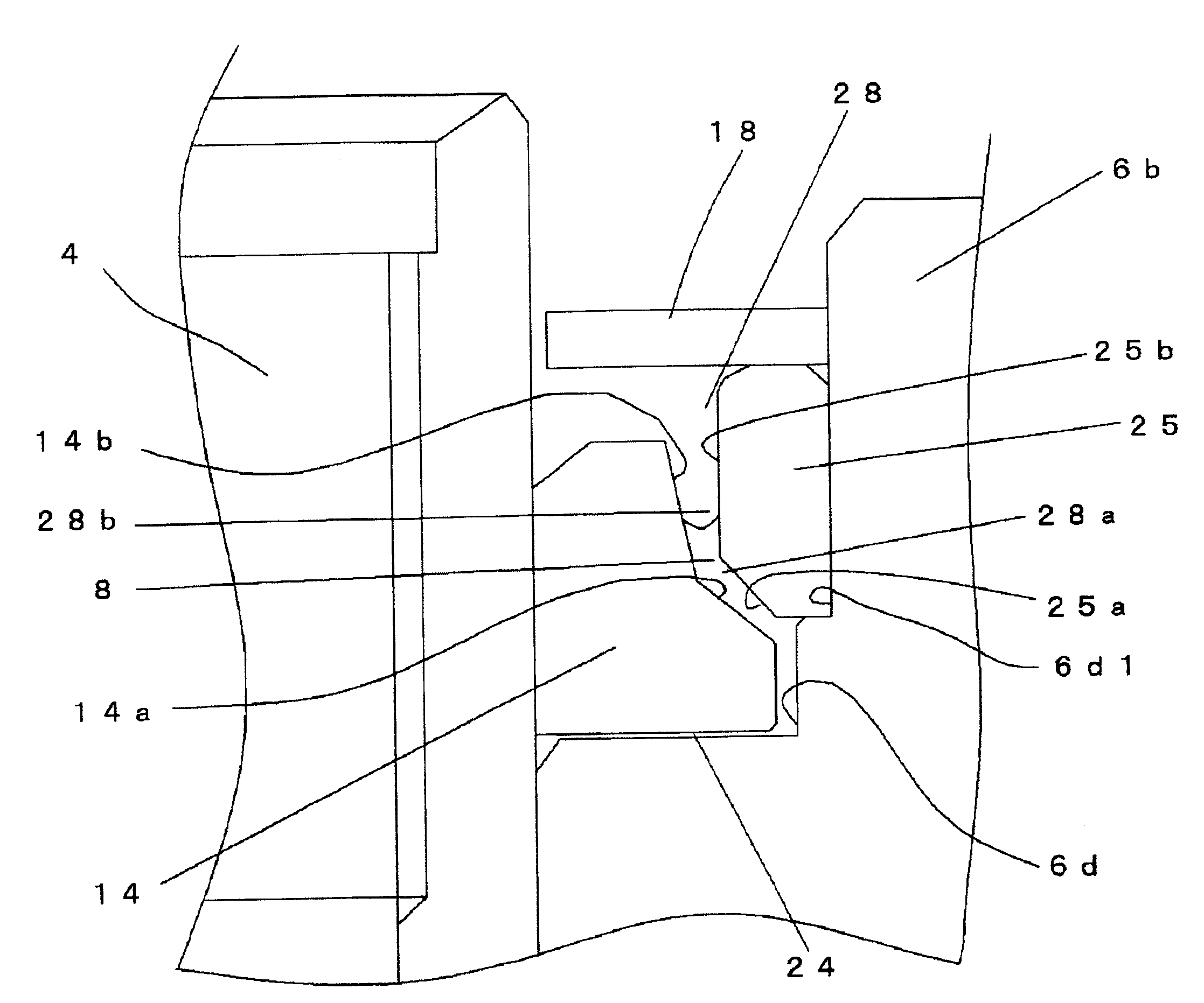
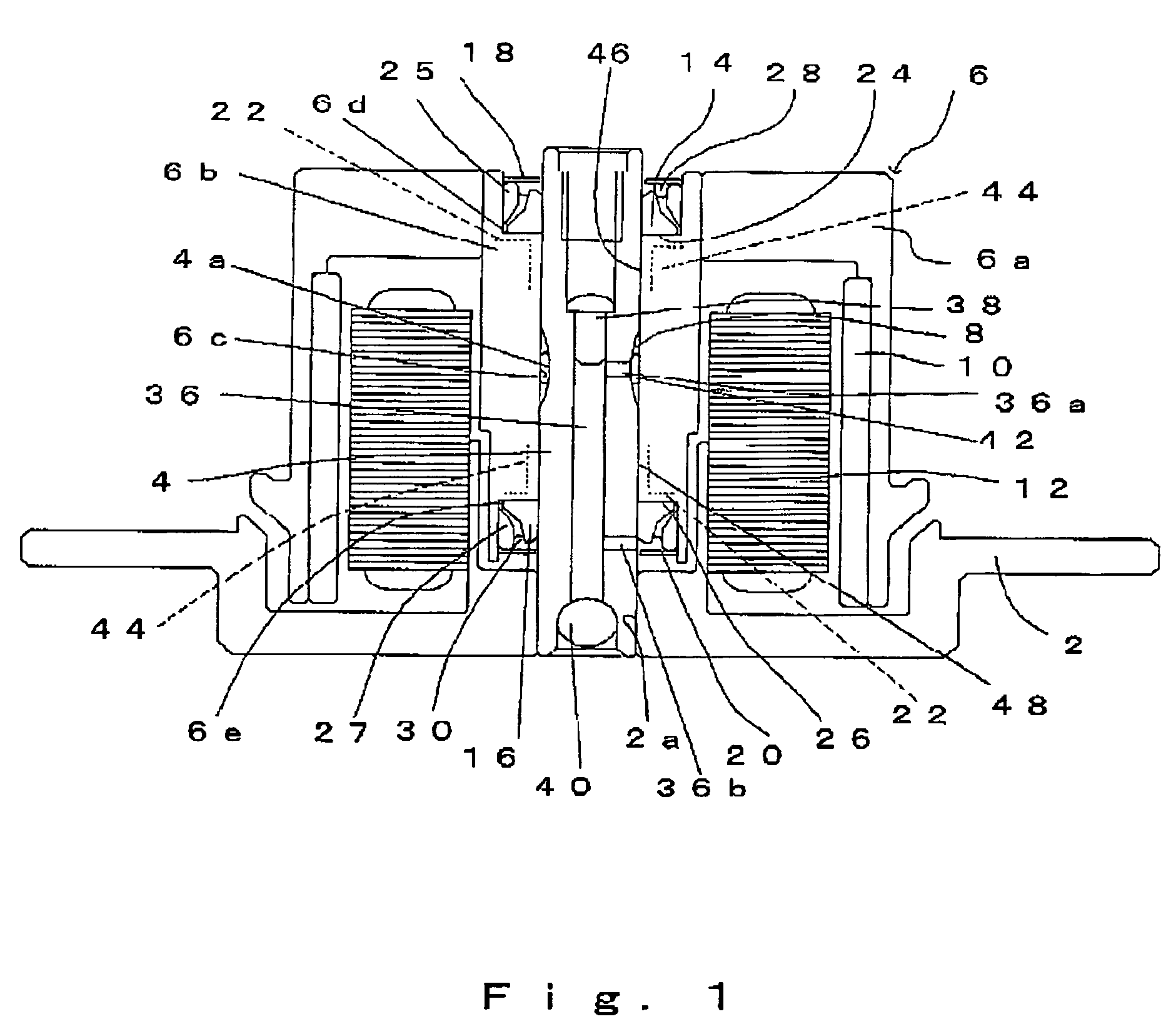
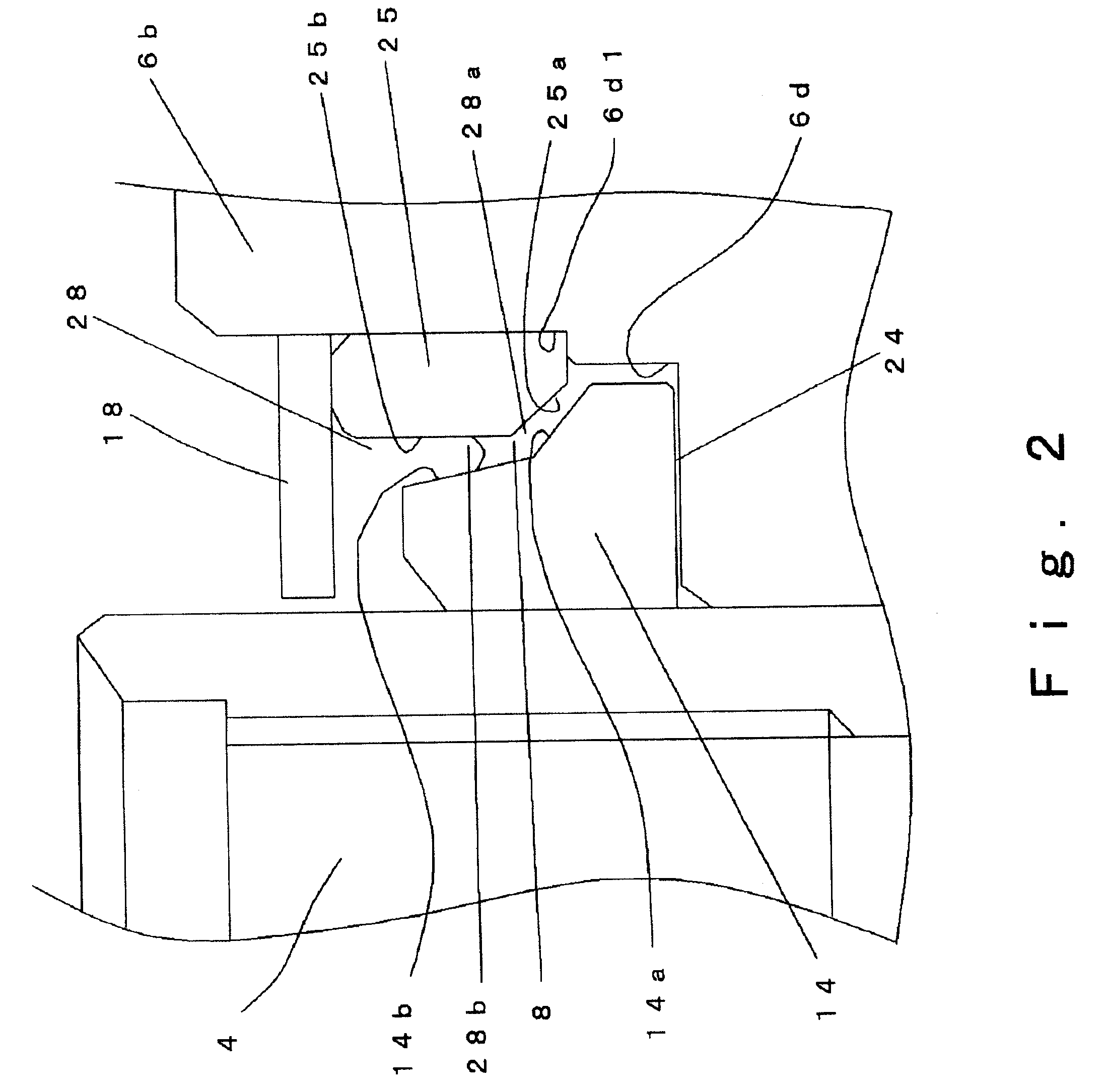
[0029]A description will be given below of an embodiment of a hydrodynamic bearing, a spindle motor using the hydrodynamic bearing and a disc drive apparatus provided with the spindle motor in accordance with the present invention with reference to FIGS. 1 to 3 and FIG. 5. In this case, in the description of the embodiment of the present invention, a vertical direction in each of the drawings is regarded as a vertical direction as a matter of convenience, however, this does not limit a direction in an actual mounting state.

[0030]A spindle motor illustrated in FIG. 1 is provided with a bracket 2, a shaft 4 which is fixed to the bracket 2, and a rotor 6 which is supported to the shaft 4 via a hydrodynamic bearing so as to freely rotate with each other.

[0031]A center hole 2a to which one end portion of the shaft 4 is fitted and fixed is formed in a center of the bracket 2 corresponding to a stationary member.

[0032]The rotor 6 corresponding to a rotating member is provided with a sleeve...


PUM

PropertyMeasurementUnit
inclination angleaaaaaaaaaa

Abstract

The present invention relates to a hydrodynamic bearing supporting a shaft and a sleeve so as to relatively rotate with respect to a rotation axis. In accordance with one example of the present invention, there is provided a hydrodynamic bearing in which a capillary seal portion is formed continuously in a bearing portion having a lubricating oil retained in a micro gap as a working fluid. The capillary seal portion is provided with a first capillary seal portion having a first radial gap, a dimension of the first radial gap being getting at least wider in accordance with increasing a distance from the bearing portion in the rotation axis, and a second capillary seal portion adjoining the first capillary seal portion and having a second radial gap, a dimension of the second radial gap being getting at least wider in accordance with increasing a distance from the bearing portion in the rotation axis. The second capillary seal portion is expanded progressively in accordance with getting toward an outer side in an axial direction.

Description

BACKGROUND OF INVENTION[0001]1. Field of the Invention[0002]The present invention relates to a hydrodynamic bearing, a spindle motor using the same and a disc drive apparatus provided with the spindle motor.[0003]2. Description of the Prior Art[0004]As a bearing for rotatably supporting a rotor of a spindle motor used for a disc drive apparatus such as a hard disc drive or the like, it is started to employ a hydrodynamic bearing which is quiet, has a low vibration and can obtain a stable rotation.[0005]As the hydrodynamic bearing mentioned above, for example, there is U.S. Pat. No. 5,423,612. FIG. 4 shows a partly schematic structure of U.S. Pat. No. 5,423,612 mentioned above as a partly enlarged cross sectional view.[0006]A thrust plate 102 is fixed to a fixed shaft 100, and a lubricating oil 106 corresponding to a working fluid is retained between an outer peripheral surface of the fixed shaft 100 positioned in a lower side of the thrust plate 102 in an axial direction, and an out...

Claims


Application Information

Patent Timeline
Patent Type & Authority Patents(United States)
IPC IPC(8): F16C32/06F16C17/10F16C33/10F16C33/74G11B19/20H02K7/08H02K21/22
CPCF16C17/107F16C33/103F16C33/74G11B19/2018F16C33/107F16C2370/12F16C33/745
Inventor OKU, YOSHITOMATSUMOTO, YUSUKE
Owner NIDEC CORP
Why Eureka
Try Eureka