Multi-directional air circulating fan

a technology of air circulating fans and multi-directional fans, which is applied in the direction of liquid fuel engines, marine propulsion, vessel construction, etc., can solve the problems of inability to allow multiple users in multiple locations to simultaneously use, and inability to achieve the effect of multiple users in multiple locations at the same tim

Active Publication Date: 2006-06-13
LASKO OPERATION HLDG LLC
View PDF3 Cites 140 Cited by
  • Summary
  • Abstract
  • Description
  • Claims
  • Application Information

AI Technical Summary

Benefits of technology

[0018]According to still another aspect of the present invention, the first and second housing further comprise respective wall members to divide the first and second interior spaces into respective inlet interior spaces and outlet interior spaces to prevent the exhaust air streams from mixing with the inlet air.

Problems solved by technology

Thus these conventional devices will not allow multiple users in multiple locations to simultaneously experience the cooling sensation provided by the device.
First, the effects experienced by the user are intermittent, in that the oscillation mechanism redirects the air stream in a direction away from the user for a period of time during an oscillation cycle.
Second, as the air stream sweeps across an area, objects within the area are effected in an undesired manner. FIG. 2 shows a conventional oscillating air movement device 200.
This may not be desirable as these objects can be dislodged from their intended place.
This dust and debris can be detrimental to, for example, respiratory conditions.

Method used


Image

  • Multi-directional air circulating fan
  • Multi-directional air circulating fan
  • Multi-directional air circulating fan

Examples


Embodiment Construction

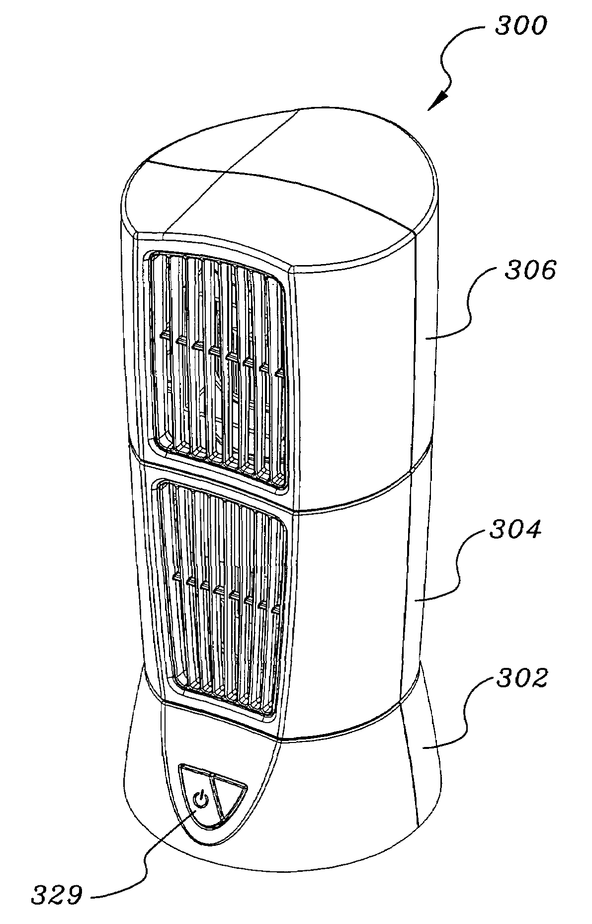
[0040]The following is a description of a multi-directional air circulation fan that allows the air stream to be divided into multiple streams which can be directed to multiple areas simultaneously. The multi-direction air circulating fan described herein also allows the user the option of allowing these multiple air streams to be stationary or the ability to oscillate the multiple air streams as desired. The described device is a multi-directional air circulating fan that further allows the oscillation feature to be adjustable to increase and / or decrease the coverage area of oscillation, thus allowing the generated air stream to return to the user's position more frequently during the oscillation cycle. In brief the multi-directional air circulating device described will allow the user the choice of fixed, enhanced oscillation and multi-directed air streams. When in use as a desk or table top fan, for example, the user benefits from the multiple air streams, one at an upper level t...


PUM


Abstract

A multi-directional air circulation device for use in a living space. The multi-directional air circulation device comprises a first housing having i) a first wall portion defining a first interior space, ii) a first air outlet, and iii) a first air directing grill adjacent to the first air outlet. At least a second housing rotatable with respect to the first housing. The second housing having i) a second a wall portion defining a second interior space, ii) a second air outlet and, and iii) a second air directing grill adjacent to the second air outlet. At least one air generator is placed in the housings and used to generate at least one air stream which is then discharged from said device as at least two independently directed air exhaust streams through the first and second air outlets into said living space.

Description

[0001]This application claims priority on provisional patent application Ser. No. 60 / 490,375 filed Jul. 25, 2003.FIELD OF THE INVENTION[0002]This invention relates generally to air circulating fans for use in a household, office or work area environment. More specifically, the present invention relates to an air generator and an air directing grill to direct the generated air stream to a desired location or multiple locations.BACKGROUND OF THE INVENTION[0003]Various air movement devices have been utilized to generate an air stream. Many of these devices have been used to specifically create an air stream for the purpose of cooling a user.[0004]The normal use of a conventional device is to provide a cooling sensation to the user by passing a current of air generated by the air moving device over the skin of an individual. The current of air that passes over an individual serves to increase the convective heat loss of the body through the natural evaporative process of moisture (e.g. ...

Claims


Application Information

Patent Timeline
Patent Type & Authority Patents(United States)
IPC IPC(8): F03B11/02F04D25/16F04D29/44
CPCF04D29/444F04D25/166
Inventor LASKO, WILLIAM E.
Owner LASKO OPERATION HLDG LLC
Why Eureka
Try Eureka