Energy-saving, anti-free flow portable pump for use with standard PVC IV tubing

a portable pump and anti-free flow technology, which is applied in the field of pumps, can solve the problems of deformation of the tubing, high power consumption of the standard tubing battery, and high cost of the pump, and achieves the effect of preventing the free flow of fluid, high accuracy, and better than 5% accuracy

Inactive Publication Date: 2006-06-13
BAXTER INT INC +1
View PDF41 Cites 46 Cited by
  • Summary
  • Abstract
  • Description
  • Claims
  • Application Information

AI Technical Summary

Benefits of technology

[0009]Another object of the present invention is to provide an ambulatory pump with high accuracy, preferably better than ±5% accuracy.
[0010]It is a further object to provide an ambulatory pump that can deliver fluid to a patient at a high volume flow rate, for example 500 ml / hour, for at least 24 hours.
[0011]It is yet another object to provide an ambulatory pump that prevents the free flow of fluid into the patient when the tubing is installed and removed.

Problems solved by technology

This leads to very high power consumption when using standard tubing.
Thus, a battery capable of powering the pump for 24 hours is very heavy and bulky.
In addition, fully collapsing the tubing deforms the tubing.
Less fluid is discharged from the tubing as the cross section becomes more elliptical, leading to negative flow rate errors.
However, there are several drawbacks in comparison to the LVP pump.
The reduced battery cannot provide the power required to completely collapse standard PVC tubing.
This specialized equipment increases the cost of using the pumps.
Even with special dedicated IV sets or silicon tubing and cassettes, many ambulatory pumps can only provide fluid to a patient for a few hours on a single battery charge.
Another problem with the infusion pumps currently in the art is the danger of free flow of fluid when the tubing is inserted or removed from the pump.
However, there is no means currently in the art to ensure that the tubing is occluded before the tubing is installed into or removed from the pump.
Thus, the tubing may accidentally become unoccluded while the tubing is outside the pump, allowing fluid to flow freely to the patient.
This overdose of fluid may be harmful or even lethal.

Method used


Image

  • Energy-saving, anti-free flow portable pump for use with standard PVC IV tubing
  • Energy-saving, anti-free flow portable pump for use with standard PVC IV tubing
  • Energy-saving, anti-free flow portable pump for use with standard PVC IV tubing

Examples


Embodiment Construction

[0034]It should be appreciated that, in the detailed description of the invention which follows, like reference numbers on different drawing views are intended to identify identical structural elements of the invention in the respective views.

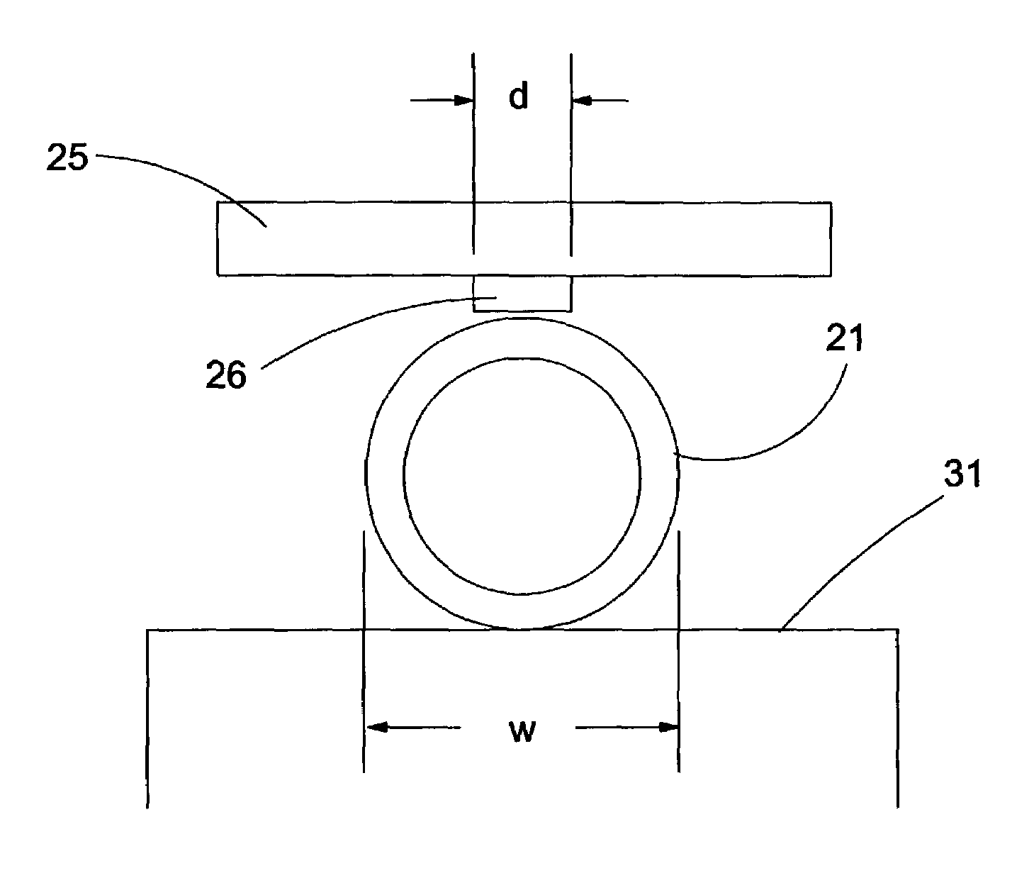
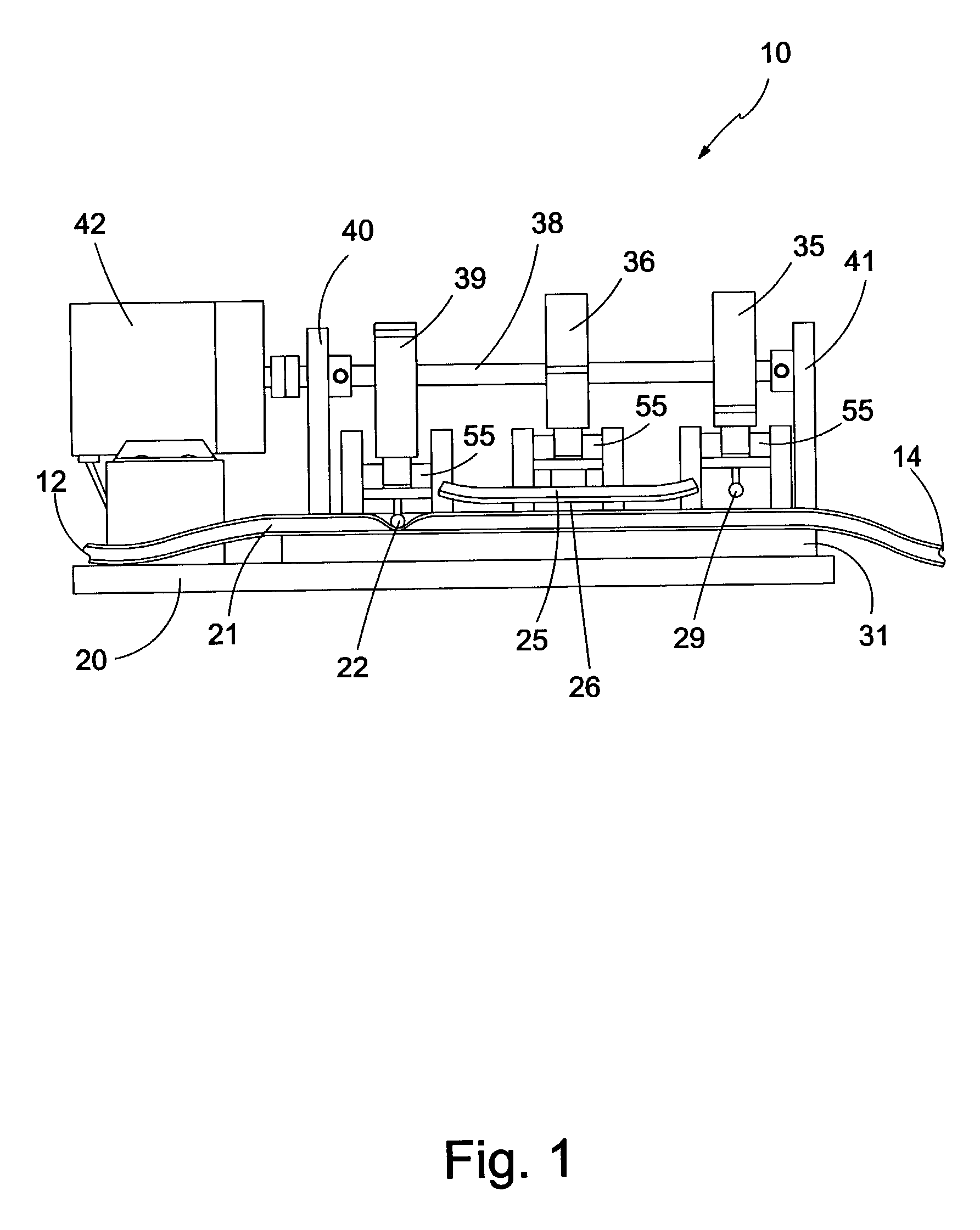
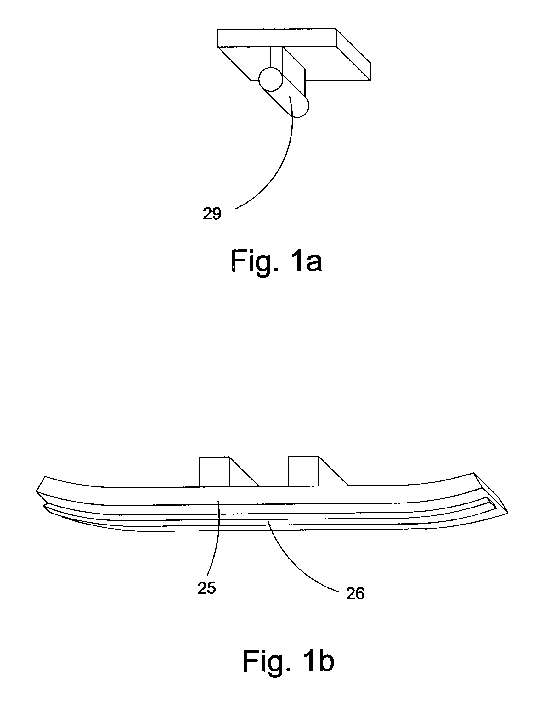
[0035]A first embodiment of the present invention is shown in FIG. 1 and generally designated 10. Apparatus 10 is an infusion pump comprising pump base 20 with tubing base 31 fixed thereto. Tubing 21 is routed over tubing base 31 underneath occlusion platens 22 and 29, and pump platen 25. Occlusion platen 22 is fixed to platen support 55. Occlusion platen 29 is fixed to platen support 55. Pump platen 25 comprises stop platen 26, and is fixed to platen support 55. Motor 42 is fixed to pump base 20. Motor 42 drives camshaft 38. Camshaft 38 is supported by shaft supports 40 and 41. Cams 35, 36, and 39 are all fixedly mounted on camshaft 38. As camshaft 38 rotates when driven by motor 42, cams 35, 36, and 39 are rotated at the same rate. Cam 35 is ...


PUM


Abstract

An apparatus for pumping fluid through tubing comprising a stop platen is disclosed. The stop platen is operatively arranged to depress a wall of the tubing along a section of a longitudinal axis of the tubing. The stop platen is narrower than the tubing along a transverse axis of the tubing. The invention further comprises a cabinet containing the stop platen, a door rotatably fixed to the cabinet, and locking means for preventing rotation of the door. The locking means are operatively arranged to be unlocked by a tubing occluder.

Description

FIELD OF THE INVENTION[0001]This invention relates to a pump for providing fluid for injection into a patient. More specifically it relates to a method and apparatus for an ambulatory infusion pump for pumping liquid through standard intravenous (IV) tubing.BACKGROUND OF THE INVENTION[0002]Infusion pumps for delivering fluid to a patient are well known in the art. Two general categories of infusion pumps known in the art are ambulatory pumps and large volume parenteral (LVP) pumps. These pumps deliver fluid to a patient through tubing at higher accuracies than gravity drip tubing delivery systems.[0003]LVP pumps are relatively large infusion pumps that can provide a fluid to a patient for 24 hours or more on a single battery charge, or indefinitely from an AC power connection. They operate on standard IV polyvinyl chloride (PVC) tubing. This obviates the need for changing IV tubing sets when a decision has been made to change from a drip tubing delivery system to the more accurate i...

Claims


Application Information

Patent Timeline
Patent Type & Authority Patents(United States)
IPC IPC(8): F04B43/08
CPCF04B43/082
Inventor CORWIN, KENNETH J.HUNGERFORD, ROGER L.SHVETSOV, YURIYWOLLOWITZ, MICHAEL H.
Owner BAXTER INT INC
Why Eureka
Try Eureka