
Golf ball

Inactive Publication Date: 2006-06-13
SUMITOMO RUBBER IND LTD
View PDF6 Cites 3 Cited by
  • Summary
  • Abstract
  • Description
  • Claims
  • Application Information

AI Technical Summary

Benefits of technology

[0009]The present inventors have taken note of a mean volume Va as an important element to influence the dimple effect. The present inventors have found that an existing golf ball having a greater mean volume Va tends to be more excellent in a flight performance if a surface area occupation ratio Y and a total volume V are equal. By setting the relationship between the surface area occupation ratio Y, the total volume V and the mean volume Va to a range which cannot be obtained by the existing golf ball, the flight performance could be enhanced.
[0012]It is preferable that a mean curvature R to be a mean value of a curvature r in a sectional shape of the dimple should be 16 mm or more. Such a golf ball presents a more excellent flight performance.
[0013]It is preferable that a mean occupation ratio y to be a value obtained by dividing the surface area occupation ratio Y by the total number N of the dimples should be 0.0022 or more. In such a golf ball, the ratio of the occupation of dimples having comparatively large areas is high. The golf ball presents a more excellent flight performance.
[0014]It is preferable that a sum X of a contour length x of the dimple and the surface area occupation ratio Y should satisfy a relationship indicated by an expression (I):X≦3882·Y+1495  (I).Such a golf ball includes a dimple pattern having a smaller total contour length X for the surface area occupation ratio Y. The golf ball presents a more excellent flight performance.
[0015]It is preferable that a ratio of the number of dimples having a contour length x of 10.5 mm or more to a total number N of the dimples should be 91% or more. Such a golf ball presents a particularly excellent flight performance.

Problems solved by technology

In addition, the acceleration of the transition of the turbulent flow increases a differentia between upper and lower separating points of the golf ball which is caused by a back spin.
In any case, a sufficient flight distance cannot be obtained.
However, a golf ball to meet the demand of the golf player has not been obtained.

Method used


Image

  • Golf ball
  • Golf ball
  • Golf ball

Examples


example 1

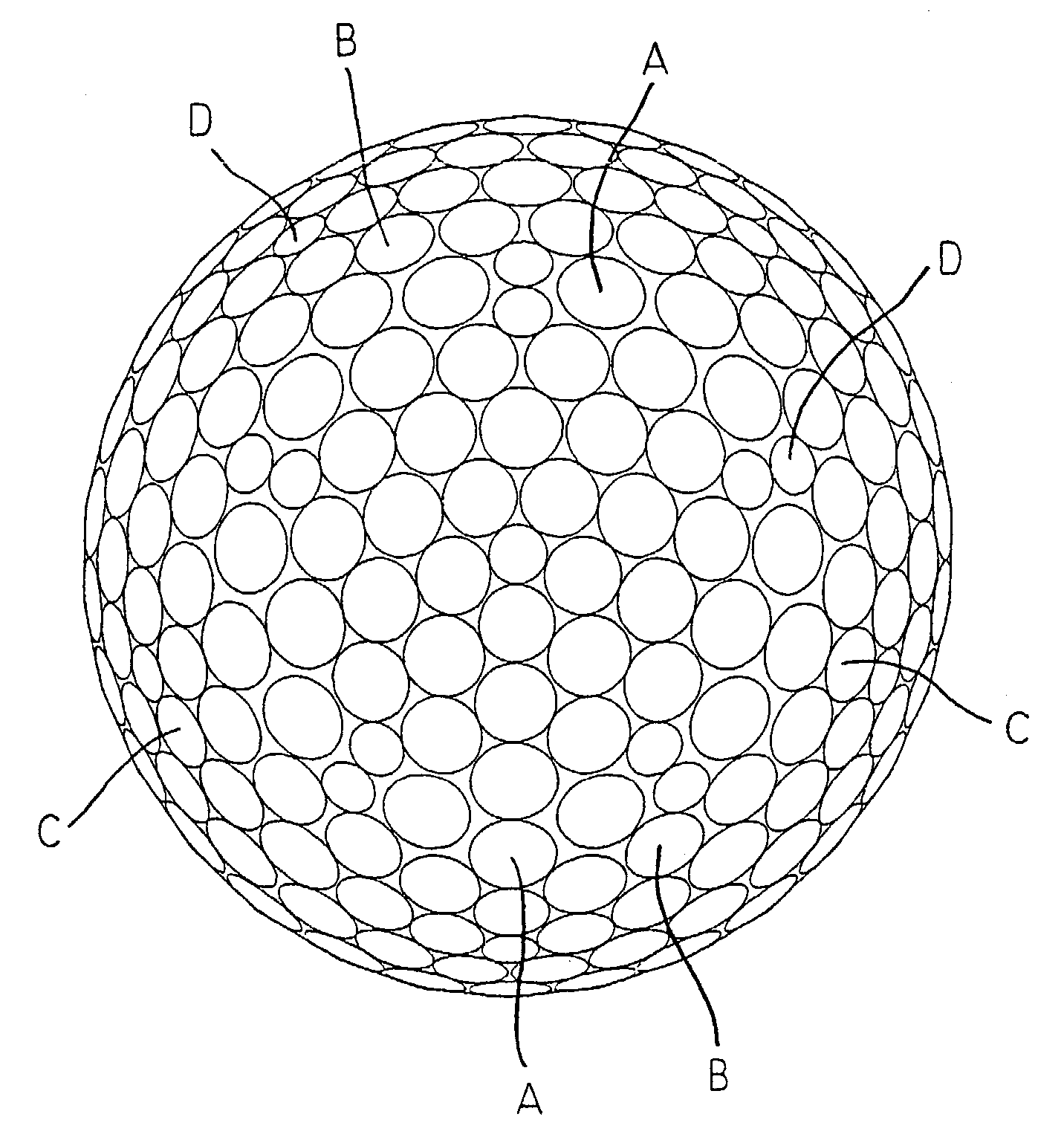
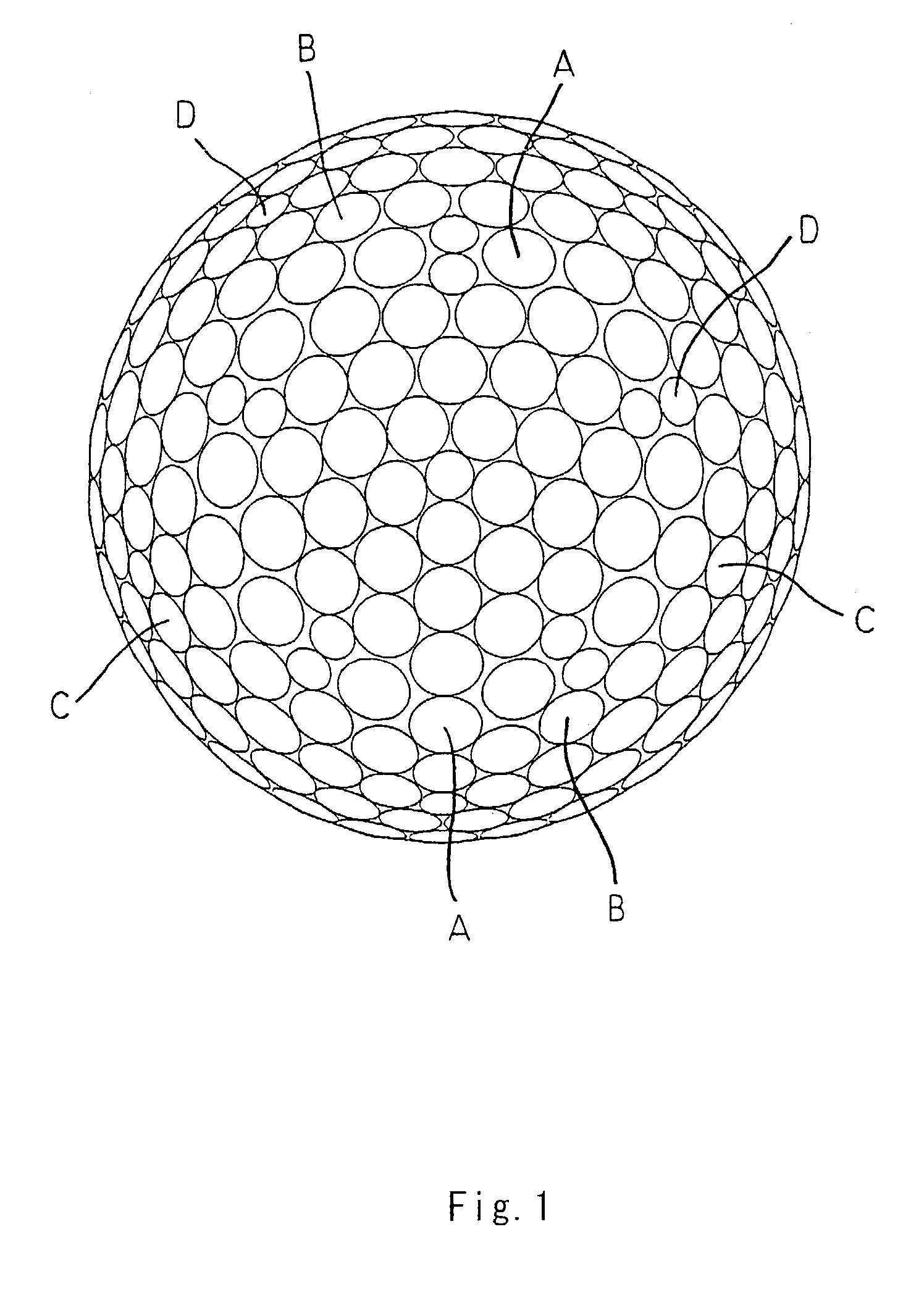
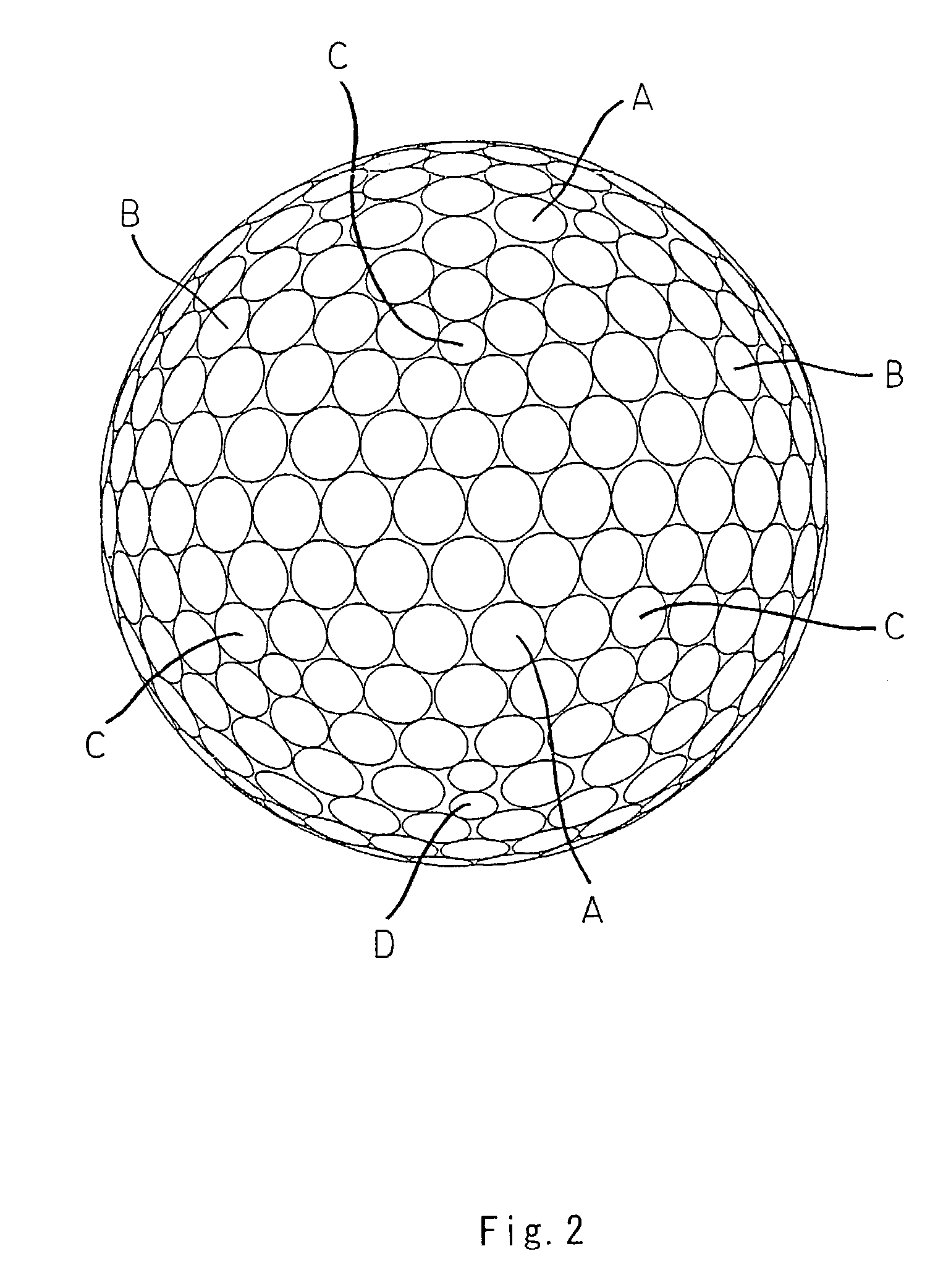
[0058]A core formed of a solid rubber was put in a mold and an ionomer resin composition was injected to form a cover around the core. The surface of the cover was coated so that a golf ball according to an example 1 which has a dimple pattern shown in a plan view of FIG. 1 and a front view of FIG. 2 was obtained. The golf ball has an outside diameter of 42.70±0.03 mm, a weight of approximately 45.4 g, and a compression of 93±2 (by an ATTI compression tester produced by Atti Engineering Co., Ltd.).

[0059]The golf ball includes 130 A dimples having a circular plane shape, a diameter of 4.5 mm and a volume v of 1.788 mm3, 150 B dimples having a circular plane shape, a diameter of 4.1 mm and a volume v of 1.351 mm3, 60 C dimples having a circular plane shape, a diameter of 3.5 mm and a volume v of 0.855 mm3, and 32 D dimples having a circular plane shape, a diameter of 2.7 mm and a volume v of 0.426 mm3. In the golf ball, a mean curvature R is 19.5 mm, a total contour length X is 4701.1...

example 2

[0060]A golf ball according to an example 2 which has a dimple pattern shown in a plan view of FIG. 4 and a front view of FIG. 5 was obtained in the same manner as in the example 1 except that the mold was changed. The golf ball includes 170 A dimples having a circular plane shape, a diameter of 4.4 mm and a volume v of 1.718 mm3, 120 B dimples having a circular plane shape, a diameter of 4.0 mm and a volume v of 1.295 mm3, 60 C dimples having a circular plane shape, a diameter of 3.4 mm and a volume v of 0.818 mm3, and 12 D dimples having a circular plane shape, a diameter of 2.3 mm and a volume v of 0.298 mm3. In the golf ball, a mean curvature R is 18.4 mm, a total contour length X is 4585.5 mm, a total volume V is 500.1 mm3, a mean volume Va is 1.382 mm3, a surface area occupation ratio Y is 0.818, and a mean occupation ratio y is 0.00226.

example 3

[0061]A golf ball according to an example 3 which has a dimple pattern shown in a plan view of FIG. 6 and a front view of FIG. 7 was obtained in the same manner as in the example 1 except that the mold was changed. The golf ball includes 72 A dimples having a circular plane shape, a diameter of 5.9 mm and a volume v of 3.836 mm3, 24 B dimples having a circular plane shape, a diameter of 4.5 mm and a volume v of 1.566 mm3, 88 C dimples having a circular plane shape, a diameter of 3.8 mm and a volume v of 1.004 mm3, 112 D dimples having a circular plane shape, a diameter of 3.6 mm and a volume v of 0.790 mm3, and 24 E dimples having a circular plane shape, a diameter of 2.7 mm and a volume v of 0.387 mm3. In the golf ball, a mean curvature R is 24.9 mm, a total contour length X is 4194.7 mm, a total volume V is 500.0 mm3, a mean volume Va is 1.562 mm3, a surface area occupation ratio Y is 0.808, and a mean occupation ratio y is 0.00252.


PUM


Abstract

A golf ball has a large number of dimples (A to D) on a surface thereof. A surface area occupation ratio Y of the dimples is 0.80 to 0.90. A total volume V of the dimples is 300 mm3 to 700 mm3. A mean volume Va to be a value obtained by dividing the total volume V by a total number N of the dimples is 1.30 mm3 or more. A mean curvature R to be a mean value of a curvature r in the sectional shape of the dimple is 16 mm or more. A mean occupation ratio y to be a value obtained by dividing the surface area occupation ratio Y by the total number N of the dimples is 0.0022 or more. A sum X of a contour length x of the dimple and the surface area occupation ratio Y satisfy a relationship indicated by an expression (I):X≦3882·Y+1495.  (I)

Description

[0001]This nonprovisional application claims priority under 35 U.S.C. § 119(a) on Patent Application No. 2002-009077 filed in JAPAN on Jan. 17, 2002, which is herein incorporated by reference.BACKGROUND OF THE INVENTION[0002]1. Field of the Invention[0003]The present invention relates to a golf ball. More particularly, the present invention relates to an improvement in a dimple of the golf ball.[0004]2. Description of the Related Art[0005]A golf ball has approximately 200 to 550 dimples on a surface thereof. The role of the dimples resides in one aspect that such dimples disturb an air stream around the golf ball during the flight to accelerate the transition of a turbulent flow at a boundary layer, thereby causing a turbulent flow separation (which will be hereinafter referred to as a “dimple effect”). The acceleration of the transition of the turbulent flow causes a separating point of air from the golf ball to be shifted backward so that a drag coefficient (Cd) is reduced, result...

Claims


Application Information

Patent Timeline
IPC IPC(8): A63B37/12A63B37/00
CPCA63B37/0004A63B37/0006A63B37/0012A63B37/0021A63B37/0017A63B37/0018A63B37/002A63B37/0016
Inventor MORIYAMA, KEIJISAJIMA, TAKAHIRO
Owner SUMITOMO RUBBER IND LTD
Learn More