Tibial component

a technology of tibial parts and components, which is applied in the field of knee joint replacement, can solve the problems of limiting the success rate of such replacements, and affecting the quality of replacements

Inactive Publication Date: 2006-06-13
BTG INT LTD
View PDF28 Cites 142 Cited by
  • Summary
  • Abstract
  • Description
  • Claims
  • Application Information

AI Technical Summary

Benefits of technology

[0009]The aim of the invention is to provide a tibial component that will cause the lateral ligament to be tightened relatively more than the medial.

Problems solved by technology

However, continuous review of clinical experience with unicompartmental meniscal knee implants has shown that problems can occur, particularly in the case of replacement of the lateral compartment.
Whilst great success has been achieved with medial compartmental replacement, dislocation of the meniscal bearing in the lateral compartment remains a problem.
The success rate of such replacements has been limited, due to the fact that the lateral soft tissues (principally the lateral collateral ligament and the ilio-tibial band) offer less certain resistance to distraction of the joint.
There is also evidence to suggest that the lateral compartment may lift off under certain circumstances, such as during single leg stance, resulting in unequal loading of the joint.
Attempts to develop total joint prosth

Method used


Image

  • Tibial component
  • Tibial component
  • Tibial component

Examples


first embodiment

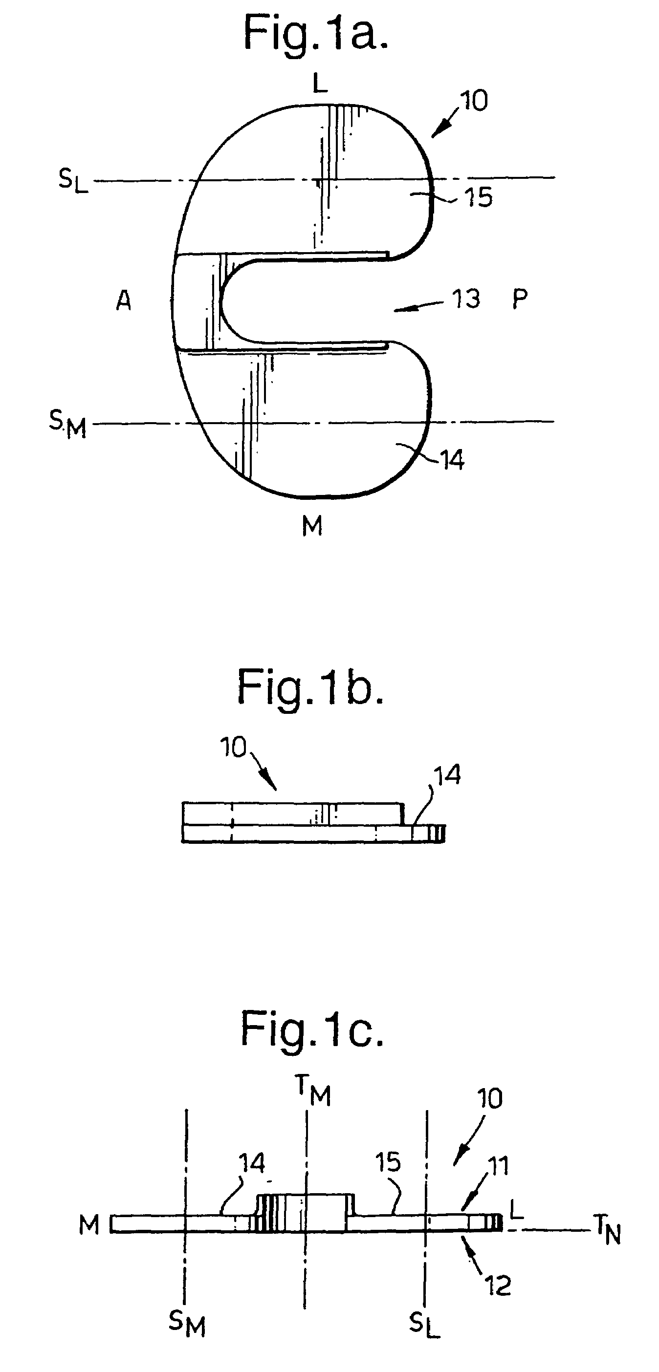
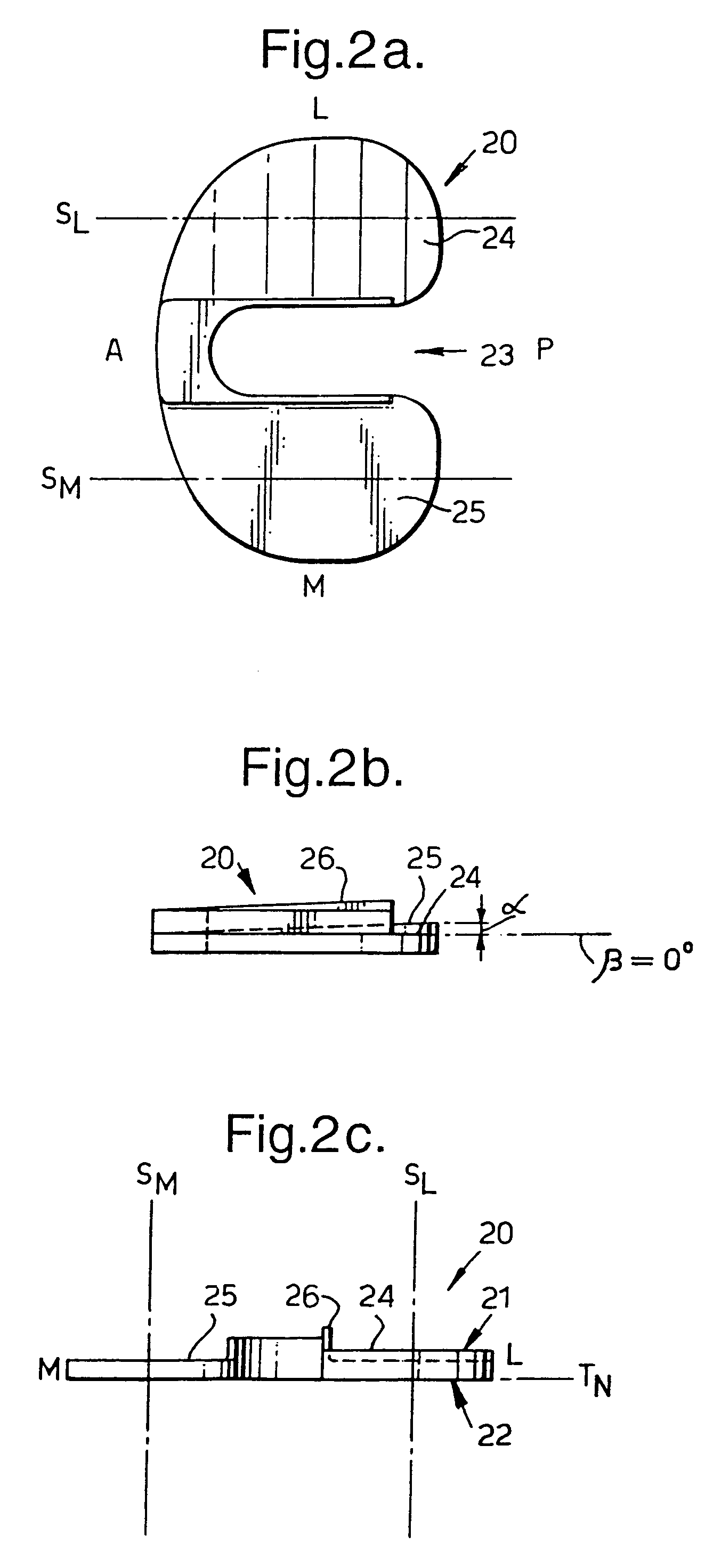
[0035]FIGS. 2 and 3 illustrate right and left versions of a bicompartmental tibial tray component 20 in accordance with the invention, similar to the-conventional tibial tray component illustrated in FIG. 1. The component also has a first, upper, major surface 21, which acts as a bearing articulation surface, and a second, lower, major surface 22, opposite the first surface, for attachment to the tibia (not shown). By adjusting the angle of inclination in the sagittal plane of the lateral and medial bearing regions (24,25) to be different, the behaviour of the prosthetic knee joint can be arranged to reduce the likelihood of dislocation in the lateral compartment.

[0036]FIGS. 2 and 3 show the plateaux (24, 25) as flat surfaces inclined to each other. In surgery, a single saw guide is used to saw the surfaces of the lateral and medial compartments of the tibia parallel to each other, preferably at an angle of approximately 7.5° to the horizontal plane, normal to the major axis of the ...

second embodiment

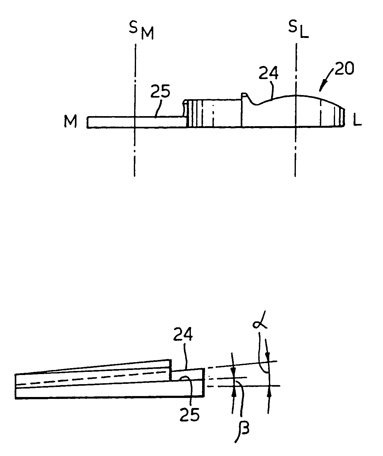
[0040]FIG. 4(a) to (c) shows the invention incorporating a component (20) for a profiled meniscal bearing to provide added stability. In this embodiment, by making the bearing surfaces of convex, curved form, the resistance to dislocation can be further enhanced. The tibial plateaux are inclined to each other in the sagittal plane as in FIG. 2, such that, in situ, a plane fitted to the surface of the bearing region in the lateral compartment (24) will be inclined at a lesser angle to the horizontal than in the medial compartment (25). The curved bearing regions (24, 25) shown are defined by convex surfaces of part-cylindrical shape. The surfaces can also be defined by convex surfaces of part-spherical shape. As shown in FIG. 4(d), if only one compartment is provided with a curved surface, advantageously, less bone removal may be required. The medial bearing region can be flat, with the lateral bearing region convex as shown in FIG. 4(d), or alternatively, the lateral bearing region ...


PUM


Abstract

A tibial knee joint prosthesis for attachment to a suitably prepared tibial bone, providing bearing portions in the lateral and medial compartments. The lateral and medial bearing surfaces of the component are inclined at different angles in the anterior to posterior direction of the knee, so that when mounted to the tibia, the lateral bearing surface of the prosthesis is higher than the medial bearing surface to the posterior side of the knee. In this way the lateral ligament is tightened progressively more than the medial ligament as the knee moves from extension to flexion, resulting in increased stability in the lateral compartment.

Description

[0001]This application is a continuation of application Ser. No. 10 / 014,920, filed Dec. 14, 2001 now abandoned, which claims priority of PCT / GB00 / 02334, filed Jun. 16, 2000, the entire content of which is hereby incorporated by reference in this application.[0002]The invention relates in general to prosthetic knee joint devices, and in particular to bi-compartmental devices for use in the lateral and medial compartments of the tibia.BACKGROUND OF THE INVENTION[0003]Considerable development has taken place in recent decades with regard to knee joint replacement. However, continuous review of clinical experience with unicompartmental meniscal knee implants has shown that problems can occur, particularly in the case of replacement of the lateral compartment. Whilst great success has been achieved with medial compartmental replacement, dislocation of the meniscal bearing in the lateral compartment remains a problem. The success rate of such replacements has been limited, due to the fact...

Claims


Application Information

Patent Timeline
IPC IPC(8): A61F2/38
CPCA61F2/389A61F2/3868
Inventor O'CONNOR, JOHN JOSEPHGOODFELLOW, JOHN WILLIAMMURRAY, DAVID
Owner BTG INT LTD
Why Eureka
Try Eureka