
Optical fiber fusion-splicer

a fusion splicer and optical fiber technology, applied in the field of optical fiber observing image processing apparatus, can solve the problems of low resolving power in comparison with other photo-taking methods, inability to increase the magnifying power of the optical system, and inability to achieve high accuracy, high resolving power, and high speed

Inactive Publication Date: 2006-06-13
FURUKAWA ELECTRIC CO LTD
View PDF8 Cites 16 Cited by
  • Summary
  • Abstract
  • Description
  • Claims
  • Application Information

AI Technical Summary

Benefits of technology

The present invention provides an optical fiber observing image processing apparatus that can automatically control the positioning of optical axes and end faces of optical fibers using image data captured by television cameras. The apparatus has an image capturing means that can capture image data from multiple television cameras and process only the desired data. The capturing modes of the image capturing means can switch automatically in synchronous with or independently from the progress of the image processing. The apparatus can also divide the field of the television camera into multiple sections to capture the image data of multiple cameras simultaneously. Overall, the invention simplifies the process of automatically controlling the positioning of optical fibers and improves the efficiency of image processing.

Problems solved by technology

(1) Since the fiber observing image processing apparatus shown in FIG. 30 has only a single television camera G, it is not suitable for high accurate positioning.
(2) In the fiber observing image processing apparatus shown in FIG. 31A since two images are photo-taken by the single television camera G, a magnifying power in the optical system cannot be increased, with the result that a resolving power is low in comparison with other photo-taking methods.
However, the circuit is complicated to make the entire apparatus expensive and bulky.
However, since the images from the respective television cameras G are renewed every 1 / 15 second, it is difficult to increase the positioning speed.

Method used


Image

  • Optical fiber fusion-splicer
  • Optical fiber fusion-splicer
  • Optical fiber fusion-splicer

Examples


first embodiment

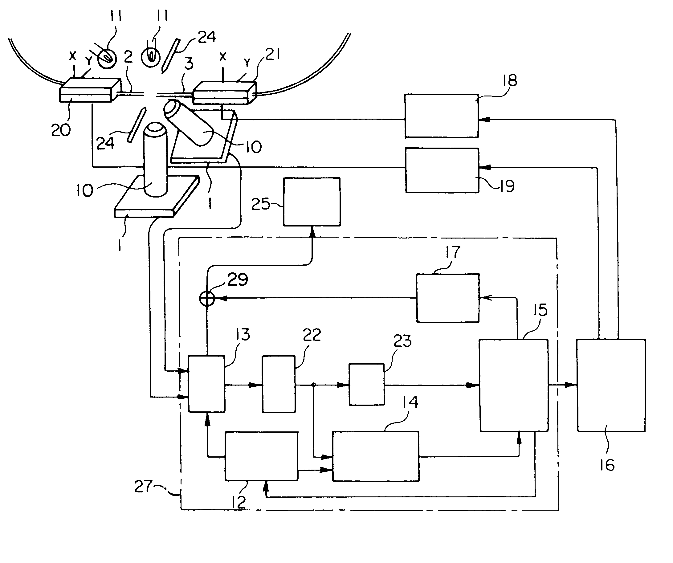
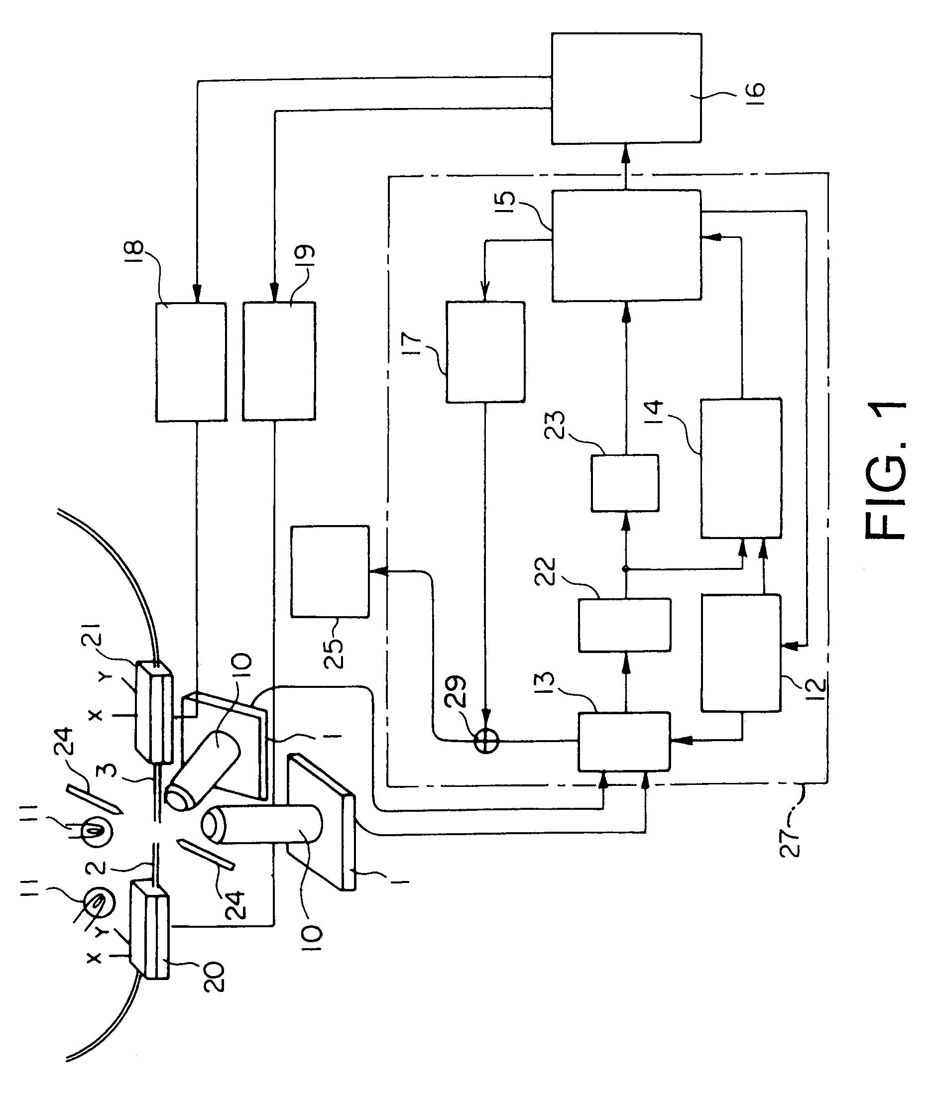
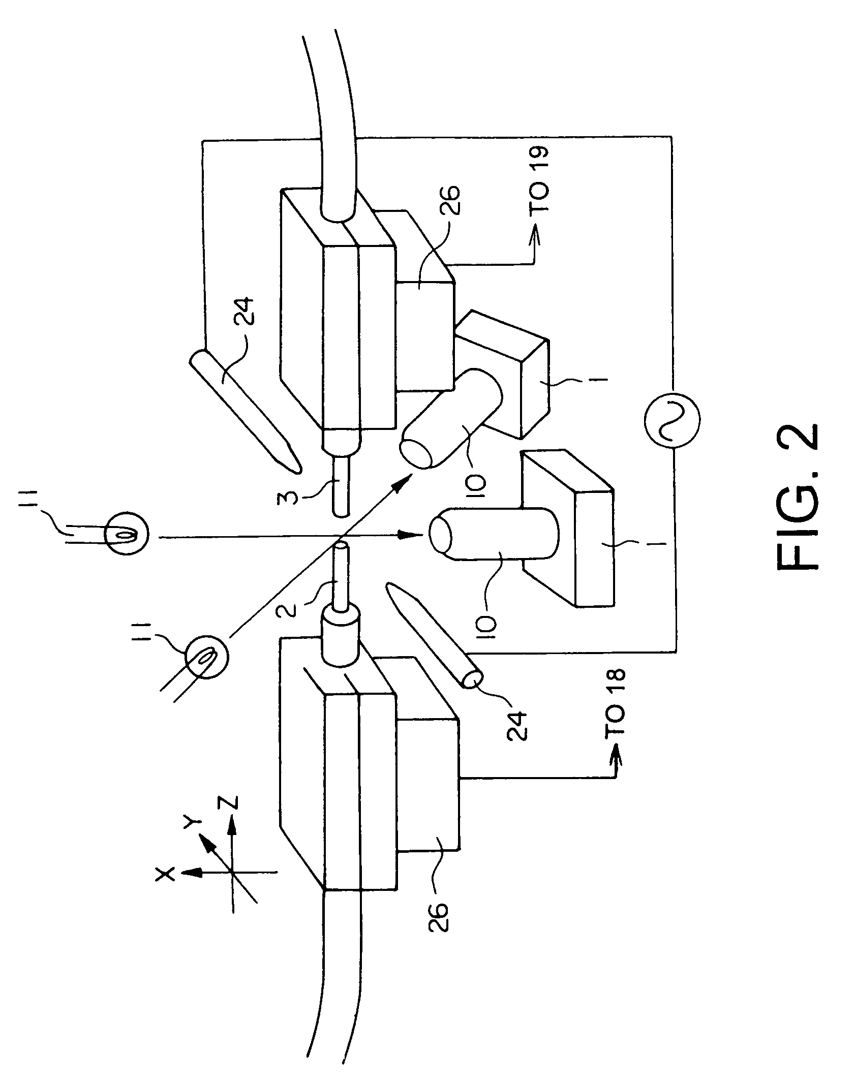
[0069]FIG. 1 is a schematic view of an entire optical fiber fusion-splicer constituted by using an optical fiber observing image processing apparatus 27 according to the present invention, and FIG. 2 is an enlarged view of an optical fiber fusion-splicing portion. In this optical fiber fusion-splicer, as shown in FIGS. 1 and 2, butted portions (portions to be butted) of optical fibers 2, 3 can be photo-taken by two (first and second) television cameras 1. Respective television cameras 1 are set to photo-take butted portions of optical fibers 2, 3 from each different angles in the direction vertical to optical axes. Each television camera 1 is constituted by attaching an incident optical system 10 for photo-taking the fibers 2, 3 in an enlarged form to a solid-state image sensor (not shown) such as a CCD. Light emitted from illumination light sources 11 opposite to the respective television cameras 1 with the interposition of the optical fibers 2, 3 pass through the fibers and is rec...

operational example

[0080]FIG. 3 shows an operating steps of the optical fiber fusion-splicer, together with images displayed on the television monitor, and FIG. 4 shows a relationship between the operating steps and the capturing modes. Now, the operating steps and the capturing modes will be described.

[0081]1. After the optical fibers 2, 3 (from which coatings were removed and in which end portions of the fibers were prepared) are set on the positioning members 20, 21 of the optical fiber fusion-splicer, when a start switch (not shown) is depressed, the images photo-taken by the first and second television cameras are captured into the data memory 14 in the capturing mode ④, and the optical fibers 2, 3 are advanced up to predetermined positions and are stopped there (steps 1 to 3 in FIGS. 3 and 4).

2. Weak discharging of electrode rods 24 is started, thereby cleaning end portions of the optical fibers 2, 3 (step 4 in FIGS. 3 and 4).

3. The images photo-taken by the first and second television cameras a...

second embodiment

[0085]FIG. 14 shows a second embodiment of an optical fiber observing image processing apparatus 27 according to the present invention. In this embodiment, a scanning converter (scanning converting means) 30 is incorporated into the optical fiber observing image processing apparatus 27 according to the first embodiment so that the image data captured in the data memory 14 can be displayed on the television monitor 25 through the scanning converter 30. In this case, two or more different transfer modes for transferring the image data between the data memory 14 and the scanning converter 30 can be provided. By selection of the transfer modes and selection of the capturing modes, for example, the following operation modes ① to ⑤ can be selected and switched on the basis of program. Incidentally, the scanning converter 30 serves to adjust longitudinal magnification, lateral magnification, longitudinal offset amount and lateral offset amount of the inputted image. Reference sign 23 in FI...


PUM


Abstract

In an optical fiber observing image processing apparatus, at least two different capturing modes is provided in an image capturing means for capturing image data from two or more television cameras, so that, by automatically switching capturing modes in synchronous with or independently from progress of the image processing, high speed processing can be achieved regardless of limitation of a data capturing speed. A scanning converting means is provided in a rear stage of the image capturing means, and a plurality of different transfer modes for transferring data between the scanning converting means and the image capturing means are prepared. Further, a delay means may be provided in a front stage of the scanning converting means.

Description

BACKGROUND OF THE INVENTION[0001]1. Field of the Invention[0002]The present invention relates to an optical fiber observing image processing apparatus in which an optical fiber set in an optical fiber fusion-splicer is photo-taken by a television camera and a photo-taken image is processed to permit automatic fusion-splice of the optical fiber. In this optical fiber observing image processing apparatus, a high speed processing speed is achieved and a circuit is simple while permitting high accurate observation with two or more television cameras.[0003]2. Description of the Related Art[0004]FIG. 30 shows an example of a conventional optical fiber fusion-splicer having an optical fiber observing image processing apparatus S. The optical fiber observing image processing apparatus S is devised so that connection of an optical fiber can be achieved at a high speed. The optical fiber fusion-splicer includes positioning members A, B shiftable in X-axis, Y-axis and Z-axis directions, and op...

Claims


Application Information

Patent Timeline
Patent Type & Authority Patents(United States)
IPC IPC(8): H04N7/18G01M11/00G02B6/255G02B6/38G02B6/42
CPCG01M11/37G02B6/2555G02B6/2551G02B6/4221G01M11/00
Inventor KOJIMA, HIDEKAZUMISHIMA, SEIRYO
Owner FURUKAWA ELECTRIC CO LTD
Learn More