Television receiving method and television receiver

a technology for receiving methods and television receivers, applied in transmission monitoring, color signal processing circuits, dc level restoring means or bias distortion correction, etc., can solve problems such as troublesome operation for selecting programs every time digital broadcasting cannot be received by users, and programs which are being viewed may be unreceivable in some cases

Inactive Publication Date: 2006-06-13
SANYO ELECTRIC CO LTD
View PDF39 Cites 64 Cited by
  • Summary
  • Abstract
  • Description
  • Claims
  • Application Information

AI Technical Summary

Benefits of technology

[0014]An object of the present invention is to provide a television receiving method and a television receiver capable of selecting, when a program having the same contents as those of a selected digital television broadcasting program is also broadcast in analog television broadcasting, broadcasting in which good audios and videos can be automatically received.

Problems solved by technology

When the television receiver is moved to the outside of a service area where the ground wave digital broadcasting has not been introduced from the area where the ground wave digital broadcasting has been introduced, therefore, a program which is being viewed may, in some cases, be unreceivable.
Even in the area where the ground wave digital broadcasting is introduced, it is considered that there is a place where the digital broadcasting is unreceivable, for example, a place concealed behind an office building particularly at the time of mobile receiving.
An operation for selecting a program every time the digital broadcasting cannot be received by the user is troublesome.

Method used


Image

  • Television receiving method and television receiver
  • Television receiving method and television receiver
  • Television receiving method and television receiver

Examples


first embodiment

[1] Description of First Embodiment

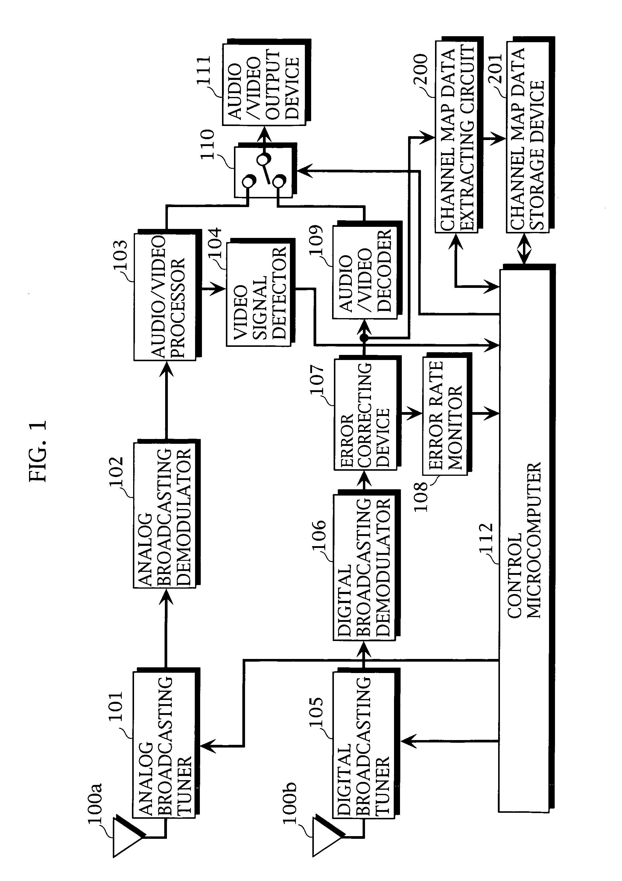
[0029]FIG. 1 illustrates the configuration of a television receiver according to a first embodiment.

[0030]In FIG. 1, the same sections as those shown in FIG. 4 are assigned the same reference numerals and hence, the description thereof is not repeated.

[0031]In this example, data representing a correspondence between an arbitrary channel of digital television broadcasting and a channel (a frequency) of analog television broadcasting on which a program having the same contents as those of a program on the arbitrary channel is being broadcast shall be sent out by digital broadcasting waves.

[0032]Reference numeral 104 denotes an analog broadcasting video signal detector for detecting whether or not an effective video signal is included in received analog broadcasting waves, which detects a horizontal synchronizing signal in a normal video signal and judges the presence or absence of the video signal depending on whether or not its period is within a de...

second embodiment

[2] Description of Second Embodiment

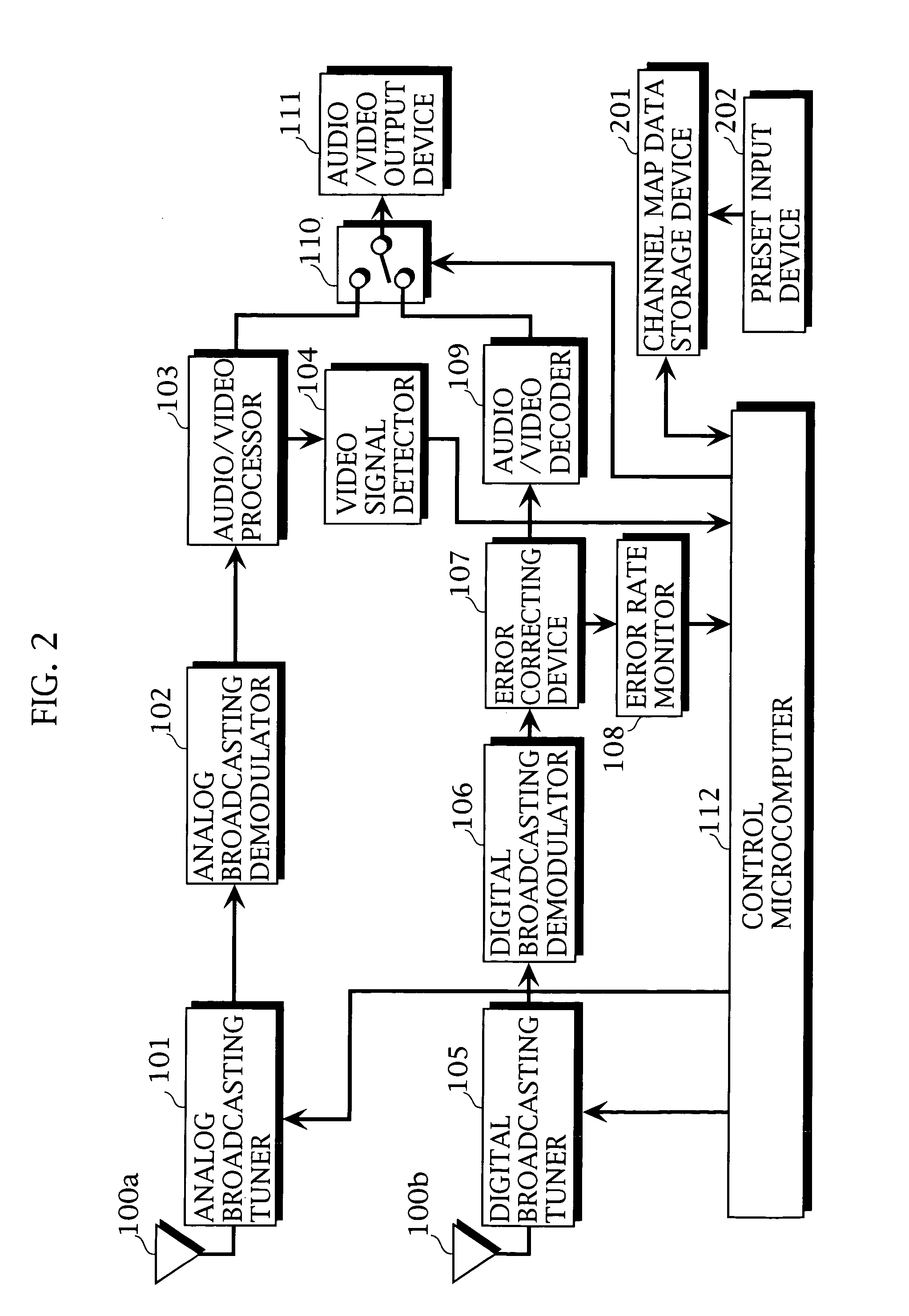
[0042]FIG. 2 illustrates the configuration of a television receiver according to a second embodiment. In the television receiver, the channel map data extracting circuit 200 in the television receiver shown in FIG. 1 is replaced with a preset input device 202. In the television receiver, a producer enters channel map information using the preset input device 202 at the time of shipment from a factory, so that the channel map information is written into a channel map data storage device 201.

[0043]Several channel map information conforming to areas are previously set in the channel map data storage device 201 at the time of shipment from a factory. It is preferable that a user selects the area used by himself or herself so that the channel map information conforming to the area is specified. Further, it is preferable that the user can individually set the channel map information.

third embodiment

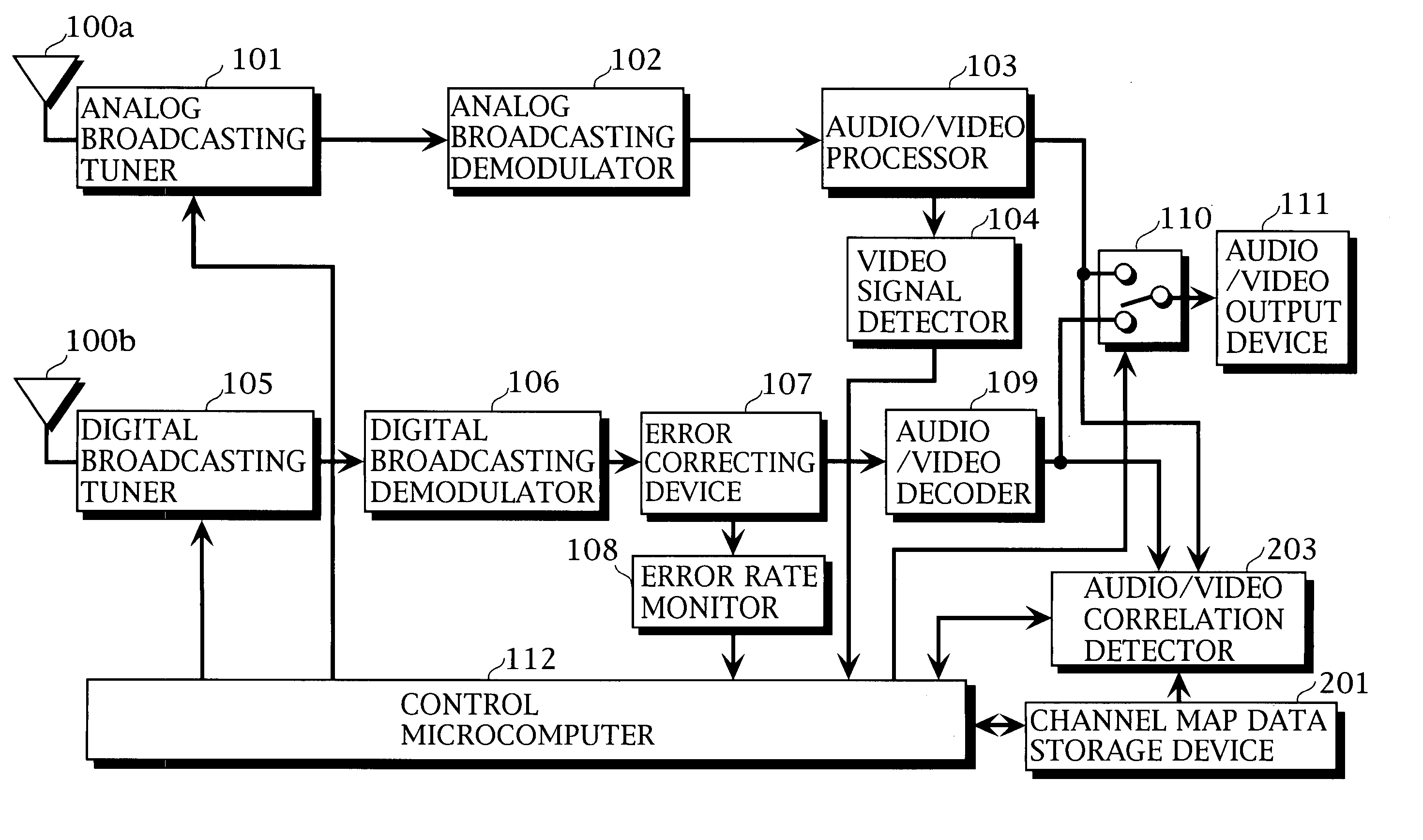
[3] Description of Third Embodiment

[0044]FIG. 3 illustrates the configuration of a television receiver according to a third embodiment.

[0045]In the television receiver, the channel map data extracting circuit 200 in the television receiver shown in FIG. 1 is replaced with an audio / video correlation detector 203.

[0046]A channel map data storage device 201 shall store default channel map information at the time of shipment from a factory, as in the above-mentioned second embodiment.

[0047]The audio / video correlation detector 203 is constituted by two series of digital memories for analog broadcasting and digital broadcasting and a correlation detecting circuit, and has the function of receiving as inputs an audio / video signal from an analog broadcasting audio / video processor 103 and an audio / video signal from a digital broadcasting audio / video decoder 109, detecting the degree of correlation between analog and digital signals, and judging whether or not analog and digital broadcasting ...


PUM


Abstract

A receiving section for digital television broadcasting and a receiving section for analog television broadcasting are provided. When a digital television broadcasting program is selected, it is judged whether or not an analog television broadcasting program having the same contents as those of the selected digital television broadcasting program is being broadcast. In a case where the analog television broadcasting program having the same contents as those of the selected digital television broadcasting program is being broadcast, when the digital television broadcasting program cannot be received, the analog television broadcasting program having the same contents as those of the selected digital television broadcasting program is received and outputted.

Description

BACKGROUND OF THE INVENTION[0001]1. Field of the Invention[0002]The present invention relates to a television receiving method and a television receiver.[0003]2. Description of the Prior Art[0004]Today, the trend of television broadcasting has been toward digitization. In Europe and the United States, digital television broadcasting has been put to practical use. In the digital television broadcasting, voices (audios) and images (videos) are digitally coded by an MPEG (Motion Picture Expert Group)-2 system, are modulated by a digital modulation system employed in each of areas, and are transmitted. As the modulation system, an OFDM (Orthogonal Frequency Division Multiplexing) system and an 8-VSB (Vestigial Sideband) system are respectively employed in Europe and the United States. Also in Japan, experiments in a system based on the OFDM system have been conducted.[0005]The digital broadcasting is characterized in that broadcasting of higher video quality and higher audio quality can...

Claims


Application Information

Patent Timeline
Patent Type & Authority Patents(United States)
IPC IPC(8): H04N5/46H04N5/44
CPCH04N5/46H04N21/42638H04N21/44209H04N21/4383H04N21/4345
Inventor IKEGUCHI, YASUYUKI
Owner SANYO ELECTRIC CO LTD
Why Eureka
Try Eureka