Optical transmission system, monitoring method therefor, optical communication apparatus, and optical external conducting apparatus

a technology of optical transmission system and monitoring method, which is applied in the direction of transmission monitoring, transmission monitoring/testing/fault-measurement system, electrical apparatus, etc., can solve the problems of difficult to use a similar method, inability to handle cases where the operation cannot be interrupted, and inability to handle the operation

Inactive Publication Date: 2006-06-13
NEC INFRONTIA CORP
View PDF8 Cites 2 Cited by
  • Summary
  • Abstract
  • Description
  • Claims
  • Application Information

AI Technical Summary

Benefits of technology

[0011]It is a first object of the present invention to provide an optical transmission system, monitoring method therefor, an optical communication apparatus, and an optical external conducting apparatus, whereby it is possible to perform monitoring of communication data without interrupting operation.

Problems solved by technology

However, with a point-to-point communication method such as ATM (Asynchronous Transfer Mode) communication, for example, it is difficult to use a similar method.
However, in the optical transmission system shown in FIG. 5, the monitor is expensive, and therefore the monitor 300 is normally connected only if a problem occurs in communication between the communication apparatus 100 and the communication apparatus 200.
A disadvantage of this is that, in order to connect the monitor 300, it is necessary to connect / disconnect optical fibers during operation and it is unavoidable to interrupt the operation.
Also, in the optical transmission system disclosed in the above described publication, the optical level is monitored, and this system thus has the disadvantage of not being able to handle cases where a fault cannot be judged by the optical level alone, such as when the optical level of the optical signal is normal but there is a problem with the data level.

Method used


Image

  • Optical transmission system, monitoring method therefor, optical communication apparatus, and optical external conducting apparatus
  • Optical transmission system, monitoring method therefor, optical communication apparatus, and optical external conducting apparatus
  • Optical transmission system, monitoring method therefor, optical communication apparatus, and optical external conducting apparatus

Examples


Embodiment Construction

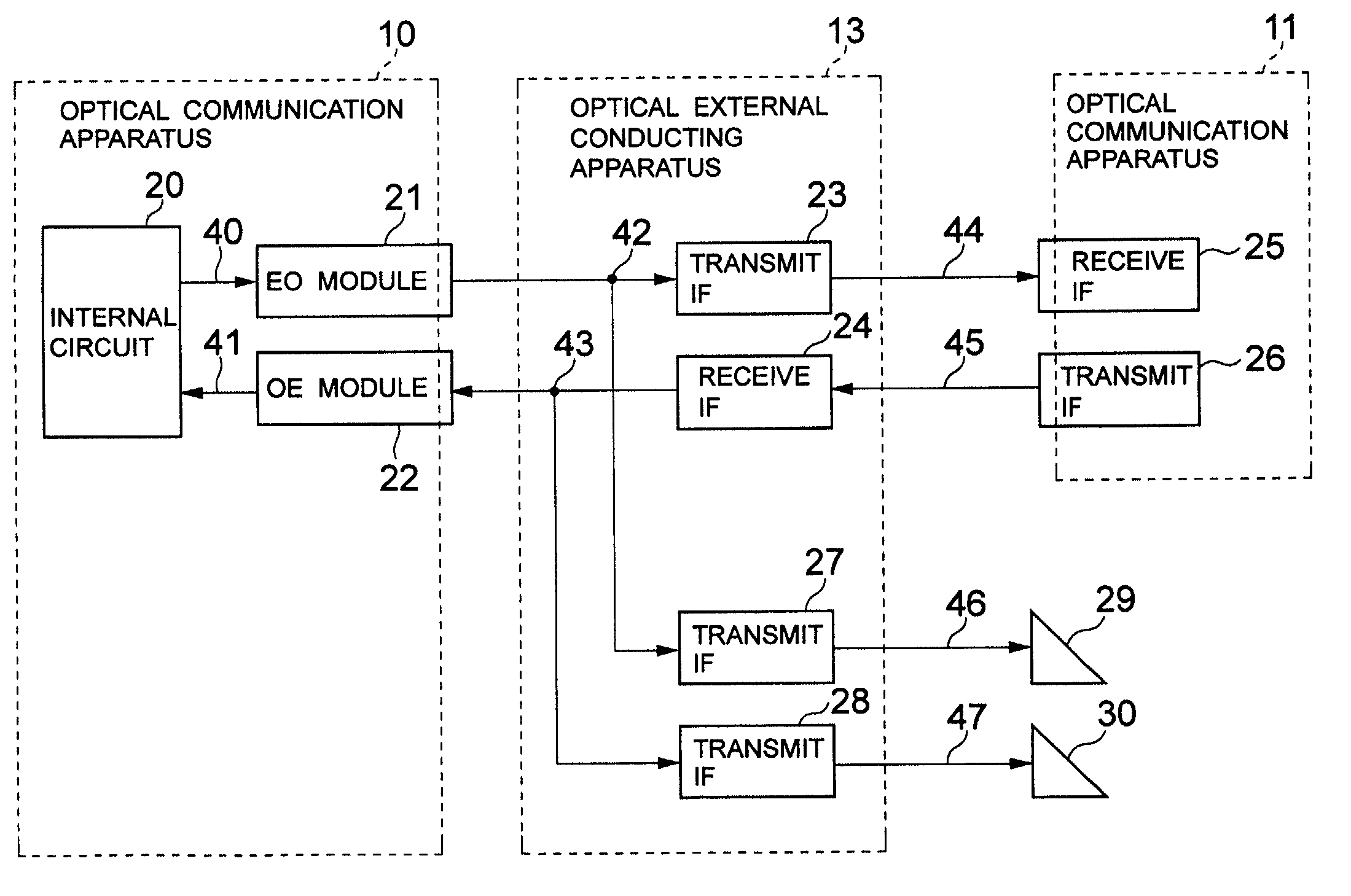
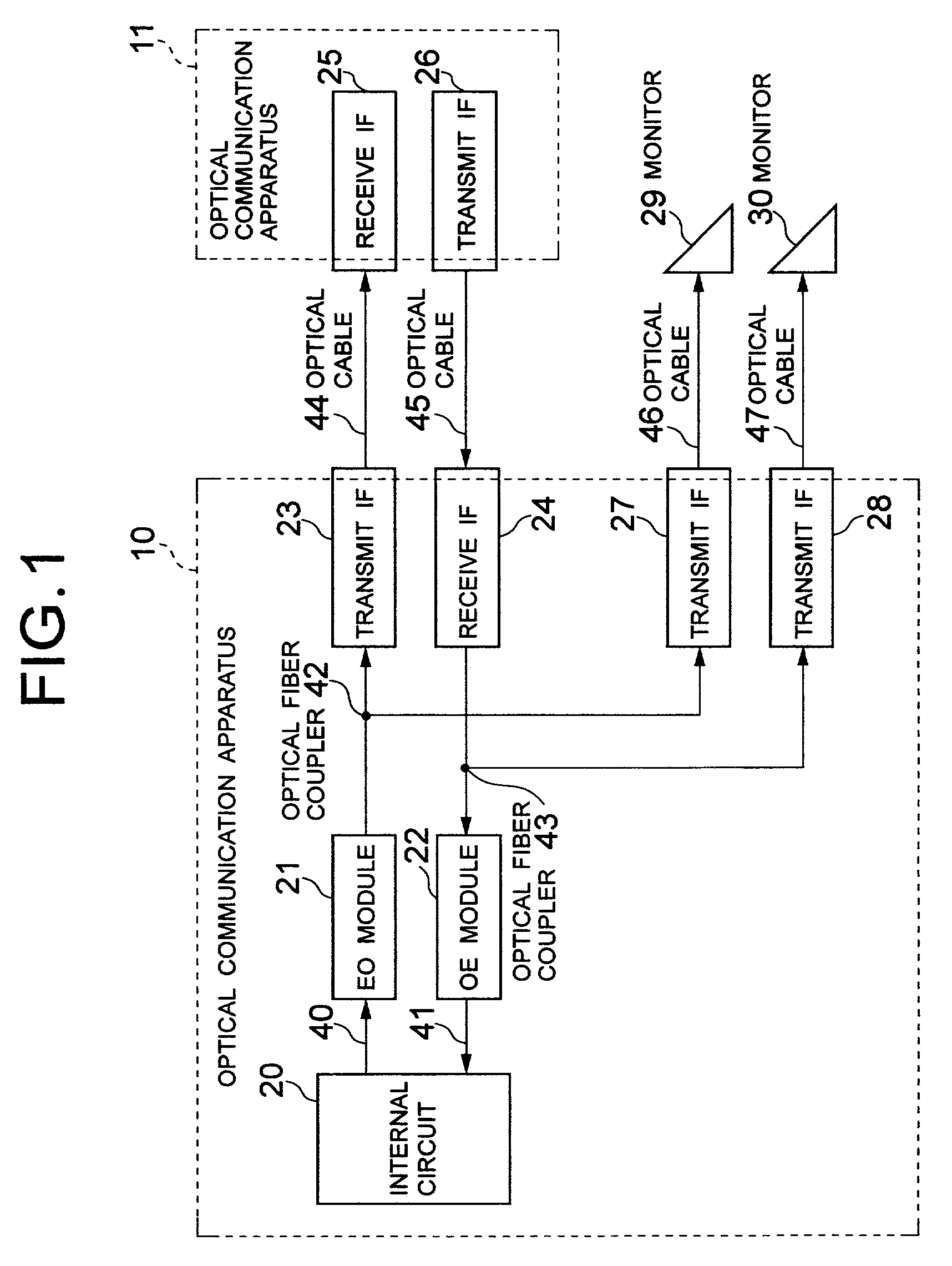
[0030]With reference now to the attached drawings, embodiments of the present invention will be described below. FIG. 1 is a block diagram of the configuration of an optical transmission system according to an embodiment of the present invention.

[0031]In FIG. 1, an optical communication apparatus 10 has an internal circuit 20 that processes electrical signals, an EO (electro-optical conversion) module 21 that converts electrical signals to optical signals, an OE (opto-electrical conversion) module 22 that converts optical signals to electrical signals, an optical transmit IF (interface) 23 that conducts optical signals to an optical communication apparatus 11 that is the communicating party, an optical receive IF 24 that receives optical signals transmitted from the optical communication apparatus 11, an optical transmit IF 27 that conducts optical signals converted by the EO module 21 to a monitor 29, an optical transmit IF 28 that conducts optical signals received by the optical r...


PUM


Abstract

To provide an optical transmission system that enables monitoring of communication data to be performed without interrupting operation. Optical signals to be transmitted by an optical communication apparatus and optical signals received by the optical communication apparatus are branched by optical fiber couplers respectively, and these branched optical signals are transmitted to transmit interfaces provided beforehand in the optical communication apparatus. Monitoring of the data contents of transmitted and received optical signals is performed by connecting these transmit interfaces to monitors, respectively.

Description

BACKGROUND OF THE INVENTION[0001]1. Field of the Invention[0002]The present invention relates to an optical transmission system, monitoring method therefor, an optical communication apparatus, and an optical external conducting apparatus, and relates in particular to an optical transmission system, monitoring method therefor, an optical communication apparatus, and an optical external conducting apparatus, whereby it is possible to perform monitoring of optical signals transmitted and received between the optical communication apparatus and its communicating party.[0003]2. Description of the Related Art[0004]With a multi-access system such as a bus-structure LAN, it is easy to monitor communication data with a monitor via a repeater or the like.[0005]However, with a point-to-point communication method such as ATM (Asynchronous Transfer Mode) communication, for example, it is difficult to use a similar method. Thus, communication data is usually monitored by inserting a monitor that ...

Claims


Application Information

Patent Timeline
Patent Type & Authority Patents(United States)
IPC IPC(8): H04B10/08H04B10/07H04B10/079H04B17/00
CPCH04B10/0799
Inventor SAITO, TAKASHI
Owner NEC INFRONTIA CORP
Why Eureka
Try Eureka