Peeling device and fixing device and image forming apparatus using the peeling device

a technology of fixing device and peeling device, which is applied in the direction of electrographic process apparatus, thin material processing, instruments, etc., can solve the problems of excessive peeling force acting on the peeling member, image defect, and melted toner being liable to adhere to the surface of the fixing roll, etc., to achieve stable peeling operation and without adversely affecting image quality.

Inactive Publication Date: 2006-06-13
FUJIFILM BUSINESS INNOVATION CORP
View PDF13 Cites 26 Cited by
  • Summary
  • Abstract
  • Description
  • Claims
  • Application Information

AI Technical Summary

Benefits of technology

[0014]The present invention has been made in view of the above circumstances, and provides a peeling device that can perform a stable peeling operation even with a recording medium that makes peeling difficult to achieve (for example, the medium is oilless, an amount of toner in a toner image is large, the toner image exists up to a leading end of the recording medium, a basis weight of the recording medium is small, the recording medium is a thin coated paper, or the like) without damaging an image, the recording medium and a rotating member including a fixing roll, and a fixing device and an image forming apparatus having the peeling device. In particular, the present invention provides a peeling device that achieves the above by applying a technique using a compressed air for sheet peeling and is of practical use without adversely affecting an image quality, and a fixing device and an image forming apparatus having the peeling device.

Problems solved by technology

However, even if the fixing roll of this type is used, because the melted toner is soft and high in viscosity, there is a fear that the melted toner is liable to adhere to the surface of the fixing roll, and the sheet is wound around the fixing roll.
However, in the case where the toner image has a large amount of toner, or the thickness of the toner image portion immediately after the fixing is relatively large, and the toner image is heated at a high temperature by the fixing roll so that an adhesion becomes large as in the case of forming a color image, a large amount of toner is adhered to a fluorine resin layer on the fixing roll surface, an excessive peeling force acts on peeling members such as the peeling claw or peeling sheet.
In this case, because the sheet with the toner image immediately after the sheet has passed through the nip portion is conveyed while being rubbed against a guide portion of the peeling member, the toner image is damaged by the peeling member, thereby easily causing an image defect.
Accordingly, since the toner immediately after the sheet has passed through the nip portion becomes low in viscosity, the image defect is more likely to occur.
(1) A reliability of the fixing roll may be reduced by various causes such as wearing of the elastic layer made of silicone rubber on the surface of the fixing roll, deterioration of the releasing property, or the elastic layer deterioration caused by oil permeated into the fixing roll.
(2) It is inferior in maintainability because oil must be periodically replenished, and there is some possibility that an oil supply system generates the trouble which is the defect of a fixed toner image on a medium due to over and uneven oiling onto a fixing device, consequently the trouble lowers the reliability of the fixing device.
(3) Oil easily remains on a sheet surface after the fixing, which easily deteriorates a touch-up ability with a ball-point pen or ink.
However, this technique is made under the conditions that plural notched grooves are defined at positions of a heat roll fixing surface (fixing roll surface) corresponding to the peeling claws, and therefore, since a flatness of the fixing roll surface cannot be ensured, a texture of a fixed image is adversely affected.
Moreover, the amount of compressed air required to peel off the sheet is enormous, resulting in a large-sized device and high costs.
In addition, there is a fear about a drawback caused by a convection of the supplied compressed air within the device, for example, toner scattering, to thereby make it difficult to put this technique in practical use.
However, in all of those techniques, the notched grooves are not formed on the surface of the fixing roll, and for that reason, a larger amount of compressed air is required for the sheet peeling, to thereby make it more difficult to put this technique in practical use (for example, refer to JP 61-59468 A) as compared with the above-mentioned technique.
In addition, the above-mentioned problem arises to some degree in image transfer in various printing systems including electrostatic transfer in the electrophotographic process and in peeling off a transfer member (photosensitive member, printing plate, or the like) from a recording medium (sheet or the like).
Similarly, the above-mentioned problem occurs in a case where the recording medium is in close contact with some rotating member (roll, belt, or the like) by some action (for example, electrostatic action), and it is necessary to peel off them from each other.

Method used


Image

  • Peeling device and fixing device and image forming apparatus using the peeling device
  • Peeling device and fixing device and image forming apparatus using the peeling device
  • Peeling device and fixing device and image forming apparatus using the peeling device

Examples


embodiment 1

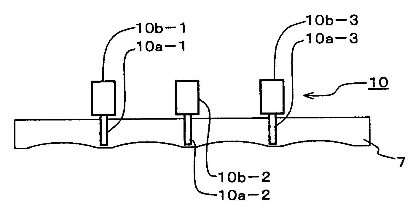
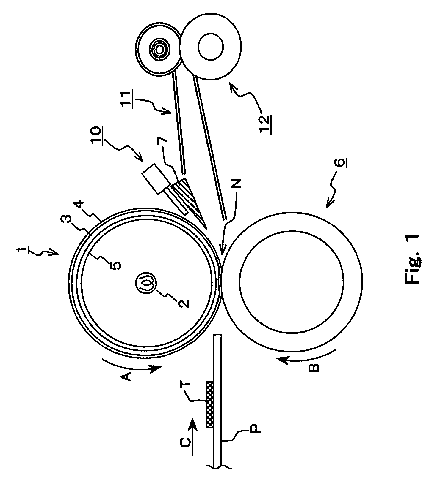
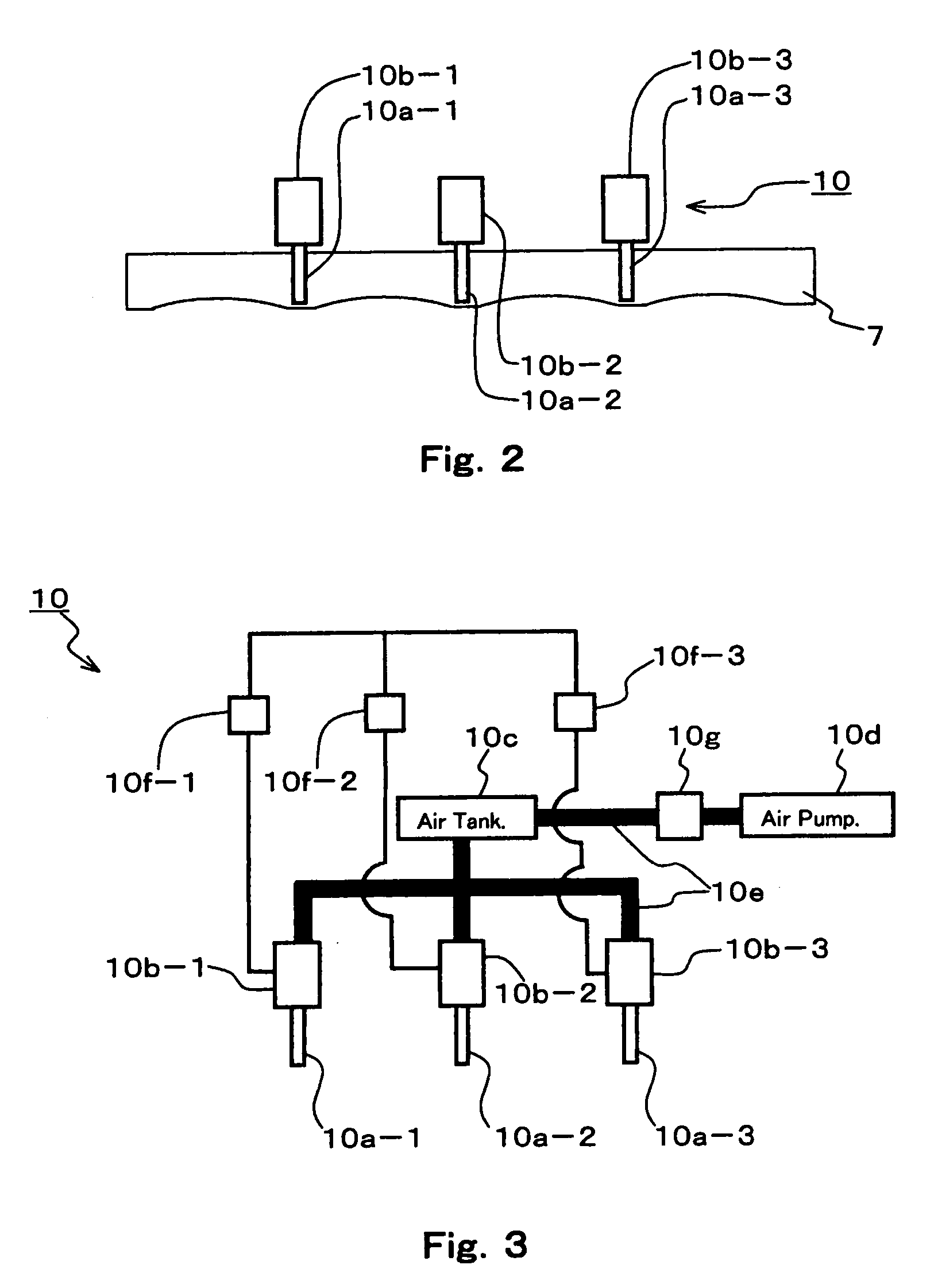
[0058]FIG. 1 is a sectional view of a fixing device including peeling devices according to Embodiment 1 of the present invention. The peeling devices of this embodiment are a combination of a first aspect and a second aspect of the present invention, and are of a two-roll system.

[0059]The fixing device shown in FIG. 1 includes a fixing roll (heating rotating member) 1 which rotates in a direction shown by an arrow A and a pressure roll (pressure rotating member) 6 which is driven to rotate in a direction shown by an arrow B opposite to the rotation direction A of the fixing roll 1 while the pressure roll 6 is in contact with the fixing roll 1. A sheet (recording medium) P carrying a toner image T made from unfixed toner on its surface is conveyed in a direction shown by an arrow C and inserted into a nip portion N formed between the fixing roll 1 and the pressure roll 6 to be heated and pressurized by the pair of rolls 1 and 6 so that the toner of the toner image T is fused, thereby...

embodiment 2

[0135]FIG. 9 is a sectional view of a fixing device adopting peeling devices according to Embodiment 2 of the present invention. The peeling devices of this embodiment are a combination of the first aspect and the second aspect of the present invention, and are of a roll-belt nip system. Since this embodiment is the same as Embodiment 1 in structure except the structure of the fixing device, in FIG. 9, members having the same function as those in Embodiment 1 are given the same reference symbols and their detailed descriptions are omitted.

[0136]The fixing device of this embodiment is essentially composed of a fixing roll 1, a pressure rotating member 16, and peeling devices 7 and 10.

[0137]The pressure rotating member 16 is essentially composed of an endless belt 21 stretched by three rolls consisting of a lead roll 18, a pressure roll 19, and a stretch roll 20, and a pressure pad (pressure member) 17 pressed against the fixing roll 1 by the endless belt 21.

[0138]The endless belt 21 ...

embodiment 3

[0149]FIG. 10 is a sectional view of a fixing device adopting a peeling device according to Embodiment 3 of the present invention. The peeling device of this embodiment is an example of the first aspect of the present invention and the fixing device is of a two-roll system. Since this embodiment is the same as Embodiment 1 in structure except the structure of the peeling device, in FIG. 10, members having the same function as those in Embodiment 1 are given the same reference symbols and their detailed descriptions are omitted. Therefore, in this embodiment, only the peeling device will be basically described.

[0150]In this embodiment, as shown in FIGS. 11(a) and 11(b), only a peeling guide plate 22 is provided as the peeling device. FIG. 11(a) is an enlarged sectional view of the peeling guide plate 22 when seen from a side opposite to the surface of the fixing roll 1 and FIG. 11(b) is an enlarged sectional view cut along H—H of FIG. 11(a). As shown in FIG. 11(b), the cross-sectiona...


PUM


Abstract

A peeling device for peeling off a sheet-like recording medium that is conveyed while adhering to a surface of a rotating member that rotates, from the rotating member, includes a peeling guide plate one side of which is close to a surface of the rotating member in a region where the surface of the rotating member advances while curving in the rotating direction, or on a downstream side of the region and which is disposed in a rotating direction of the rotating member, and an edge surface of the peeling guide plate including at least one convex portion. An air jetting unit jets a pulsed compressed air toward a gap between the surface of the rotating member and the one side of the peeling guide plate that is from a region interposed between the surface of the rotating member and the surface of the peeling guide plate that faces the surface of the rotating member.

Description

FIELD OF THE INVENTION AND RELATED ART STATEMENT[0001]The present invention relates to an image recording apparatus, and more particularly to a peeling device which is applicable in a fixing device or a transferring and simultaneous fixing device for use in an image recording apparatus of an electrophotographic process such as an electronic copying machine or a facsimile machine, and a fixing device and an image forming apparatus using the peeling device.[0002]Up to now, in an image recording apparatus of the electrophotographic process such as an electronic copying machine or a facsimile machine, as a fixing device that fixes a toner image that has been transferred to the surface of a sheet, there has been widely employed a fixing device (fixing device of a two-roll system) in which the sheet onto which the toner image has been transferred is allowed to pass through a nip portion formed by a pair of rolls composed of a fixing roll and a pressure roll, and the toner image is fused t...

Claims


Application Information

Patent Timeline
Patent Type & Authority Patents(United States)
IPC IPC(8): G03G15/20B65H29/54G03G15/14
CPCG03G15/2028
Inventor BABA, MOTOFUMIUEHARA, YASUHIRO
Owner FUJIFILM BUSINESS INNOVATION CORP
Why Eureka
Try Eureka