
Gathering and picking device

a technology for picking and gathering, applied in harvesters, applications, agricultural tools and machines, etc., can solve problems such as still occurring conveying problems, and achieve the effect of reducing the dimensions of the conveying elemen

Inactive Publication Date: 2006-06-20
MASCHFAB KEMPER
View PDF15 Cites 16 Cited by
  • Summary
  • Abstract
  • Description
  • Claims
  • Application Information

AI Technical Summary

Benefits of technology

[0005]A conveying element is arranged on the side of the picking gap located opposite the gathering element and assists in the introduction of the plants into the picking gap by the gathering element. The conveying element is rotated about a predominantly vertical axis.
[0006]This makes it possible to use a relatively flat conveying element such that the gathering device comprising the conveying element and the gathering element also has a very flat structure. The conveying element can be realized in less complex fashion than conventional screw conveyors and chain conveyors of the prior art. In addition, the weight and manufacturing costs of the conveying element are reduced, at the same time, the service life is extended. If the distance between the conveying element and the gathering element is made sufficiently small, it is also possible to realize a cleaning effect since the conveying element is able to remove plant residues from the gathering element.
[0008]The plants are effortlessly conveyed into the picking gap by the conveying element that, like the gathering element, rotates about a predominantly vertical axis. This means that another conveying element that is arranged on the point of the picking roll and that extends in the vicinity of the picking gap usually can be eliminated. And it is only desirable that the ends of the picking rolls are located approximately beneath the inlet of the picking gap. The picking rolls can therefore be made shorter and manufactured more cost effectively. In addition, it is now possible to arrange the stripping plate closer to the ground. This provides certain advantages in the collection of lodged corn. The ends of the picking rolls on the inlet side may be provided with screw conveyors in order to simplify the introduction of the plants. However, it would also be conceivable to increase the length of at least one picking roll.
[0009]In order to improve the introduction of the plants into the picking gap by the cooperating gathering and conveying elements, it is practical if their operating envelopes overlap. This enables the two elements together to introduce the plant into the picking gap without problem.
[0013]Since the plants are conveyed along the picking gap by the gathering element, it is sufficient for the conveying element to end approximately at the inlet of the picking gap. This makes it possible to reduce the dimensions of the conveying element.

Problems solved by technology

However, conveyance problems may still arise under certain harvesting conditions.

Method used


Image

  • Gathering and picking device
  • Gathering and picking device
  • Gathering and picking device

Examples


Embodiment Construction

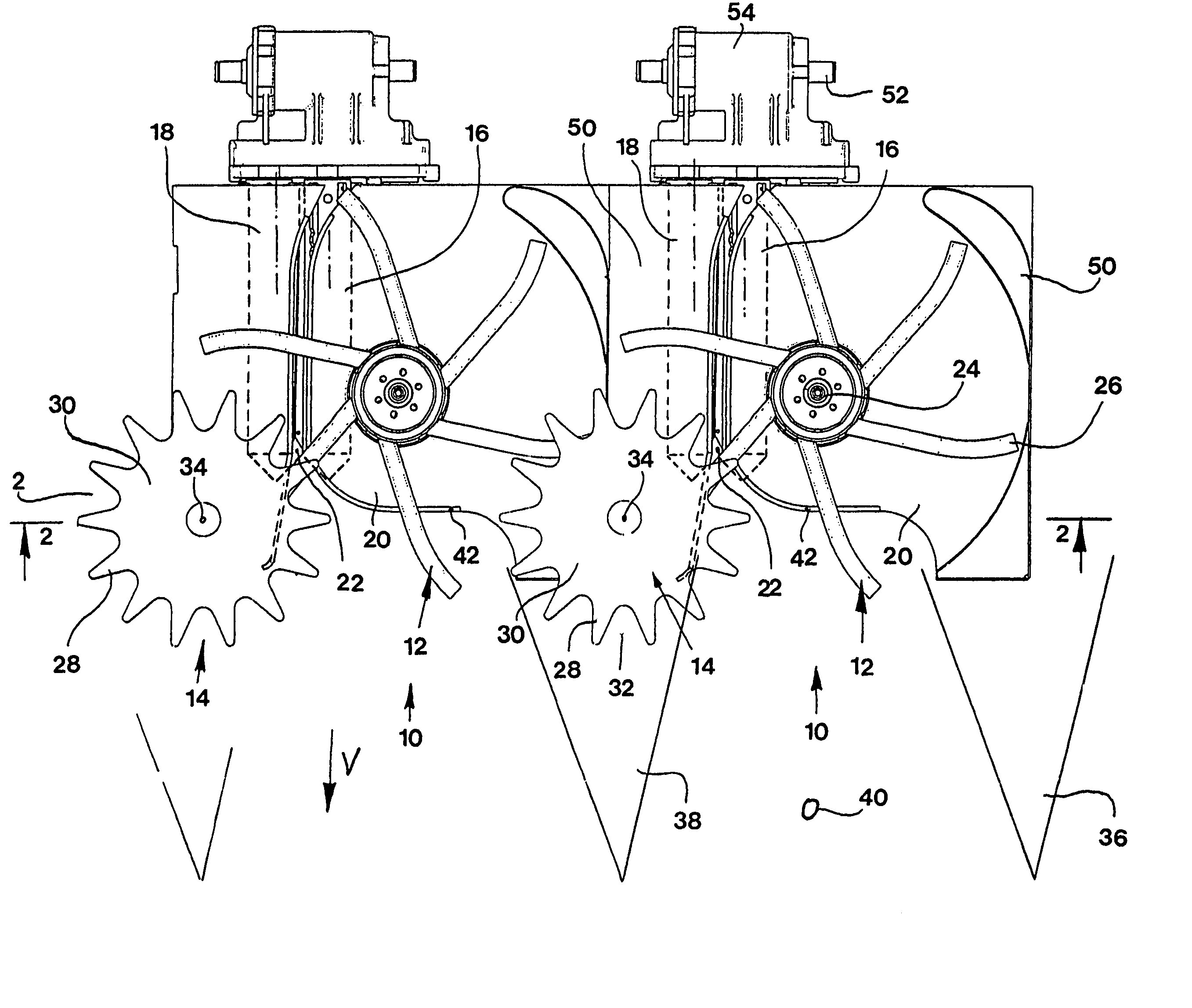
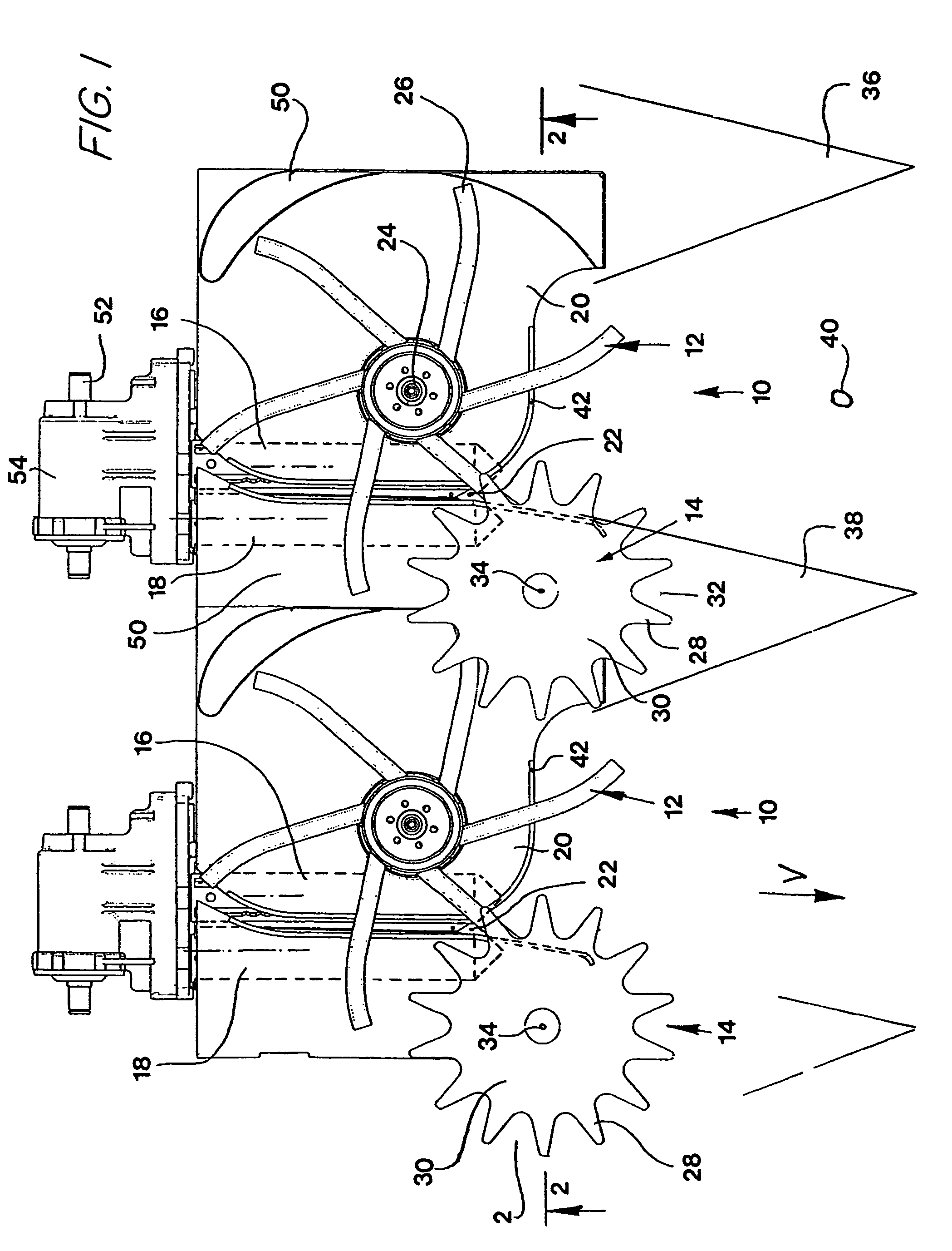
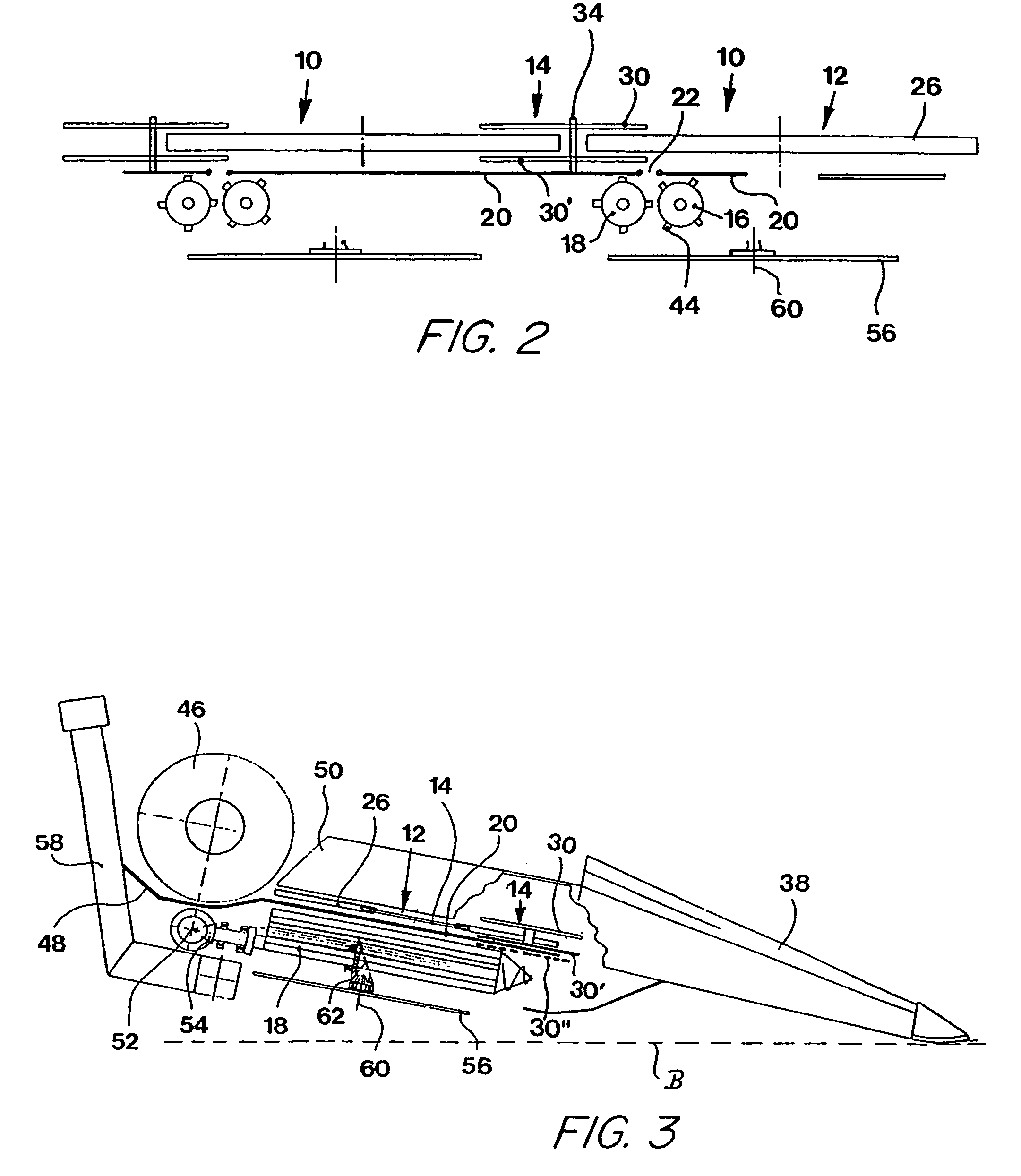
[0017]Two gathering and picking devices 10 of a corn picking attachment for a combine are illustrated in FIG. 1. A complete corn picking attachment usually comprises a series of gathering and picking devices 10. However, it would also be conceivable for the corn-picking attachment to be provided with only one gathering and picking device 10.

[0018]The gathering and picking device 10 contains a gathering element 12 for grasping and taking in the plants to be harvested, a conveying element 14, a first picking roll 16 and a second picking roll 18, wherein the picking rolls are arranged beneath a picking gap 22 located in a stripping plate 20.

[0019]Relative to the forward driving direction V, the gathering element 12 is located on the left side of the picking gap 22 and the conveying element 14 is arranged on the right side of the picking gap 22. The gathering element 12 and the conveying element 14 are arranged such that they are rotatable about predominantly vertical and parallel axes ...


PUM


Abstract

A gathering and picking device having a gathering element arranged on a first side of a picking gap. The gathering element is rotated about a predominantly vertical axis and is provided with carrier elements arranged to grasp standing plants and to introduce them into the picking gap in cooperation with a conveying element. The conveying element is arranged upstream and above the inlet of the picking gap on the side of the picking gap opposite from the gathering element. A picking unit is operable to move the plants downwardly through the picking gap, such that useful parts of the standing plants are separated.

Description

FIELD OF THE INVENTION[0001]The present invention is directed to a gathering and picking device with a gathering element that is arranged on a first side of a picking gap and a conveying element is arranged on the second side of the picking gap upstream from the inlet end of the picking gap, the gathering element and the conveying element rotate about predominantly vertical axes.BACKGROUND OF THE INVENTION[0002]U.S. Pat. No. 4,377,062 A describes a corn picker, in which a screw conveyor is arranged above the picking rolls. This screw conveyor conveys the plant stalks into and through the picking gap. A lower gathering wheel is located beneath the picking gap at the inlet side, i.e., the side of the picking gap located opposite the screw conveyor. An upper gathering wheel is arranged above the screw conveyor coaxially to the lower gathering wheel. The gathering wheels serve for conveying the plants into the picking gap.[0003]DE 100 28 887 A describes another corn harvesting attachmen...

Claims


Application Information

Patent Timeline
Patent Type & Authority Patents(United States)
IPC IPC(8): A01D45/02
CPCA01D45/021
Inventor RICKERT, CLEMENSBONGERT, DIRK
Owner MASCHFAB KEMPER
Learn More