Combustion type power tool having fin in low turbulent combustion region within combustion chamber

a technology of combustion chamber and fin, which is applied in the direction of stapling tools, nailing tools, combustion engines, etc., can solve the problems of insufficient thermal vacuum and insufficient thermal vacuum, and achieve the effect of reducing the drop in drive energy

Inactive Publication Date: 2006-06-20
KOKI HLDG CO LTD
View PDF1 Cites 32 Cited by
  • Summary
  • Abstract
  • Description
  • Claims
  • Application Information

AI Technical Summary

Benefits of technology

[0009]In a combustion-type nail driver 801 shown in FIG. 13, a fan 14 and combustion-chamber fins 136 are provided in a combustion chamber 26. Following ignition by an ignition plug 15, the fan 14 promotes the stirring and mixing of air with combustible gas in the combustion chamber 26. At this time, a turbulent combustion (a combustion of mixture gas in a turbulent state) is generated rapidly in a high turbulent-combustion region H, thereby driving a piston 25 downward.
[0010]However, in the combustion-type nail driver 801, the combustion-chamber fins 136 protrude significantly into the high turbulent-combustion region H. In other words, the combustion-chamber fins 136 has a large surface area in the high turbulent-combustion region H. Thus the combustion-chamber fins 136 adversely cool (or draw heat from) combusted gas when the turbulent combustion is generated in the high turbulent-combustion region H. Therefore the combustion-chamber fins 136 hinder the mixture gas from combusting and expanding, resulting in a drop in drive energy.
[0013]In view of the above-described drawbacks, it is an objective of the present invention to provide a combustion-type power tool which can reduce a drop in drive energy and can move a piston back to an initial position reliably.

Problems solved by technology

However, if the number of the combustion-chamber fins 136 is insufficient or if the combustion-chamber fins 136 are not provided at all, sufficient thermal vacuum is not generated or, in a worse case, the thermal vacuum is not generated at all.

Method used


Image

  • Combustion type power tool having fin in low turbulent combustion region within combustion chamber
  • Combustion type power tool having fin in low turbulent combustion region within combustion chamber
  • Combustion type power tool having fin in low turbulent combustion region within combustion chamber

Examples


Embodiment Construction

[0037]A combustion-type power tool according to embodiments of the present invention will be described while referring to the accompanying drawings wherein like parts and components are designated by the same reference numerals to avoid duplicating description.

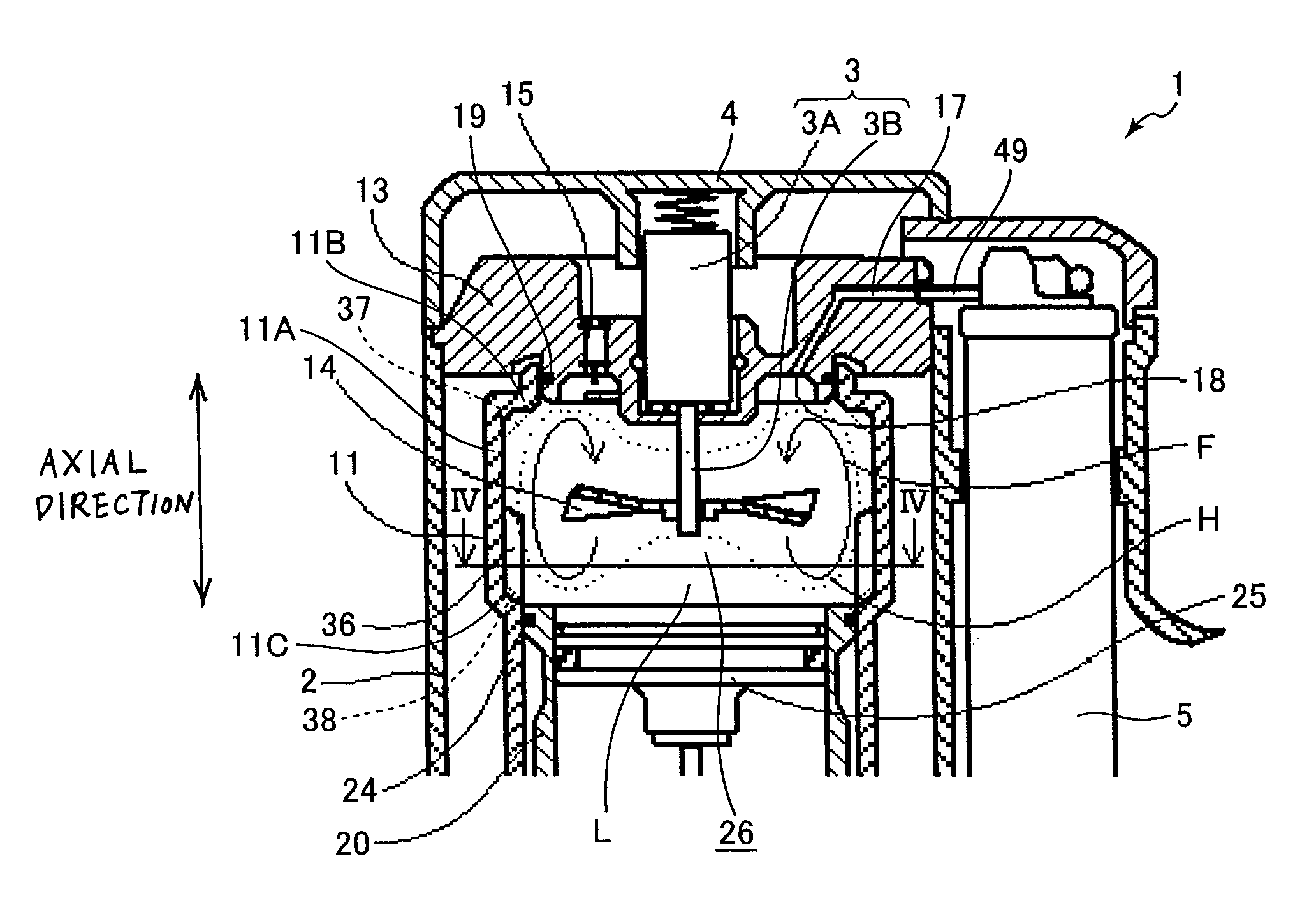
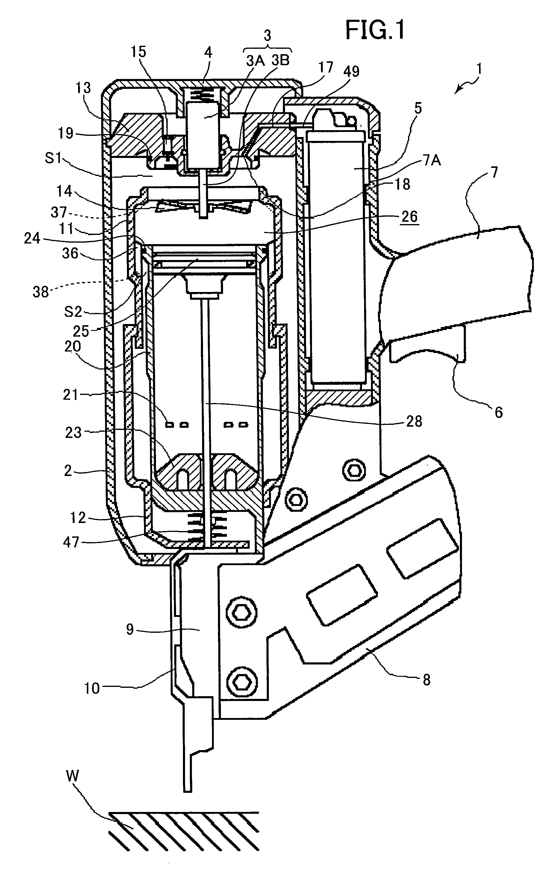
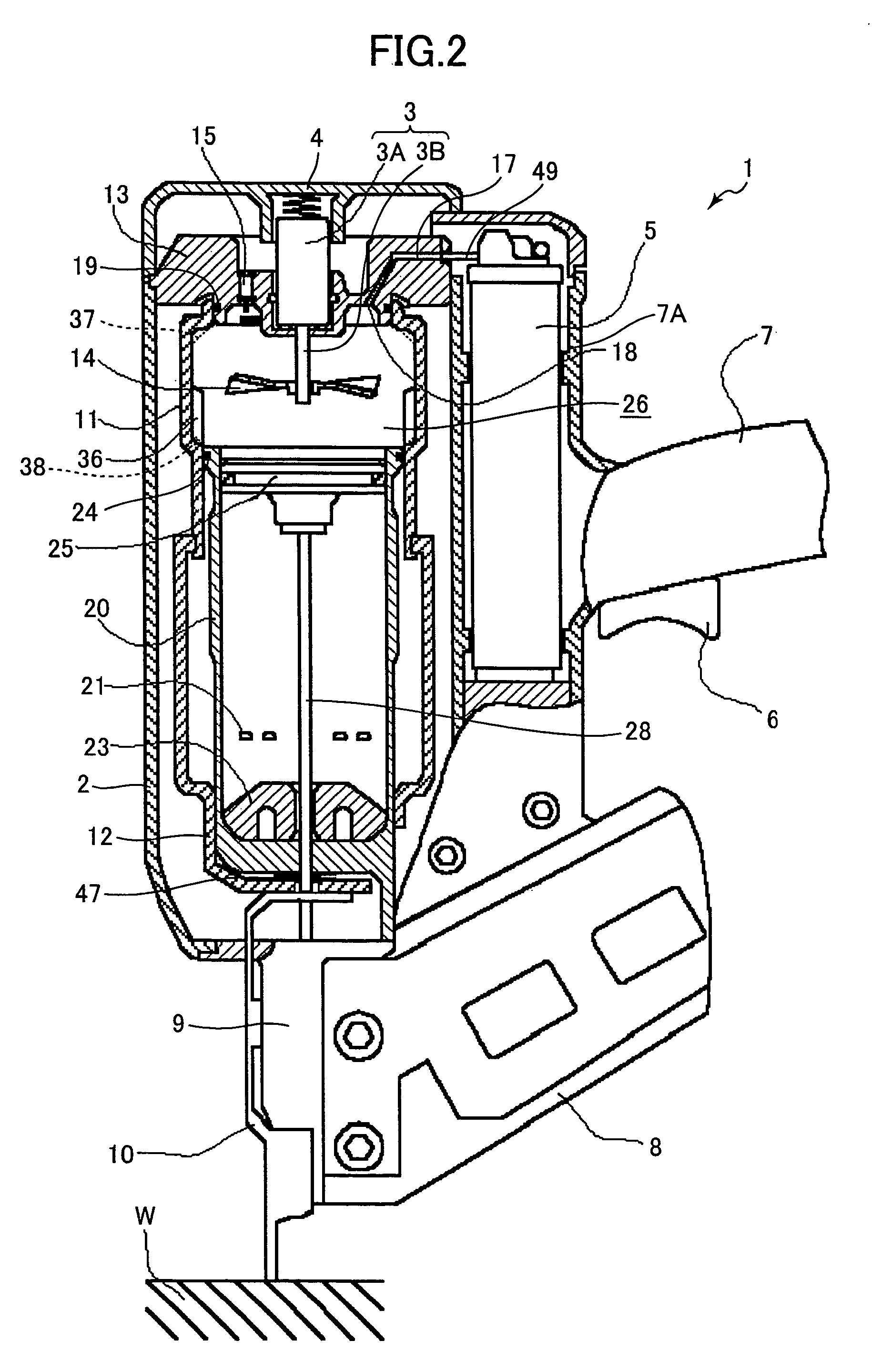
[0038]A combustion-type power tool according to a first embodiment of the present invention will be described with reference to FIGS. 1 through 5. The embodiment pertains to a combustion-type nail driver. The combustion-type nail driver 1 has a main housing 2 constituting an outer frame. The main housing 2 has a top portion provided with a head cover 4 in which an intake port is formed, and has a bottom portion formed with an exhaust port (not shown).

[0039]A handle 7 extends from a side of the main housing 2. The handle 7 includes a canister housing 7A juxtaposed to the main housing 2. A gas canister 5 containing therein a combustible liquefied gas is detachably disposed in the canister housing 7A. The handle 7 has a trigger s...


PUM

PropertyMeasurementUnit
pressureaaaaaaaaaa
shapeaaaaaaaaaa
heightaaaaaaaaaa

Abstract

A combustion-chamber frame is disposed in a housing of a combustion-type power tool and is movable in a longitudinal direction in interlocking relation to a push lever. The combustion-chamber frame is abuttable on a head portion to provide a combustion chamber in cooperation with the head portion and a piston. A fan is disposed in the combustion chamber and is connected to an output shaft of a motor so as to be rotatable with the output shaft for promoting turbulent combustion of air-fuel mixture. The fan and the combustion-chamber frame define, within the combustion chamber, a high turbulent-combustion region in which the turbulent combustion is rapidly generated and a low turbulent-combustion region outside the high turbulent-combustion region. A fin is disposed at at least one of the combustion-chamber frame, the head portion, and the piston to protrude into the combustion chamber. The fin is located within the low turbulent-combustion region.

Description

BACKGROUND OF THE INVENTION[0001]1. Field of the Invention[0002]The present invention relates to a combustion-type power tool, and more particularly, to a combustion-type fastener driving tool in which liquidized gas is ejected from a gas canister into a combustion chamber, mixed with air and ignited to drive a piston, thus generating power to drive nails or the like.[0003]2. Description of Related Art[0004]A conventional combustion-type driving tool generally includes a housing, a handle, a trigger switch, a head cap, a combustion-chamber frame, a push lever, a cylinder, a piston, a driver blade, a motor, a fan, a gas canister, an ignition plug, an exhaust-gas check valve, an exhaust cover, a magazine, and a tail cover. The head cap is disposed at one end of the housing and is formed with a combustible gas passage. The handle is fixed to the housing and is provided with the trigger switch. The combustion-chamber frame is movable in the housing in the lengthwise direction thereof. T...

Claims


Application Information

Patent Timeline
Patent Type & Authority Patents(United States)
IPC IPC(8): F02B41/00B25C1/04B25C1/08
CPCB25C1/08
Inventor NISHIKAWA, TOMOMASAAKIBA, YOSHITAKAFUJISAWA, HARUHISA
Owner KOKI HLDG CO LTD
Why Eureka
Try Eureka