
System and method for inserting a weft thread

a weft thread and system technology, applied in the field of system and method for inserting weft threads, can solve the problems of relatively complicated and expensive ep 0 554 222 a1, drastically increasing the consumption of compressed air, and the method which is described, so as to ensure the quality of cloth. unobjectionable, the effect of low cost and complexity of system components

Inactive Publication Date: 2006-06-20
SULTEX AG
View PDF8 Cites 10 Cited by
  • Summary
  • Abstract
  • Description
  • Claims
  • Application Information

AI Technical Summary

Benefits of technology

[0005]An object of the present invention is to make available a system and a method for inserting a weft thread into a shed of an air jet weaving machine which have a control of the air jets which is simple and ideal with respect to the compressed air consumption, which manage with a comparatively low cost and complexity of system components, and which ensure an unobjectionable cloth quality. A further object of the invention is to make available an air jet weaving machine including a system of this kind and for carrying out a method of this kind.
[0020]In a preferred embodiment, the time required for the insertion of the weft thread is additionally determined and compared with a predetermined insertion time, and the difference between the time required for the insertion of the weft thread and the predetermined insertion time is used to regulate the pressure and / or the blowing time and / or the flow through the air nozzles.
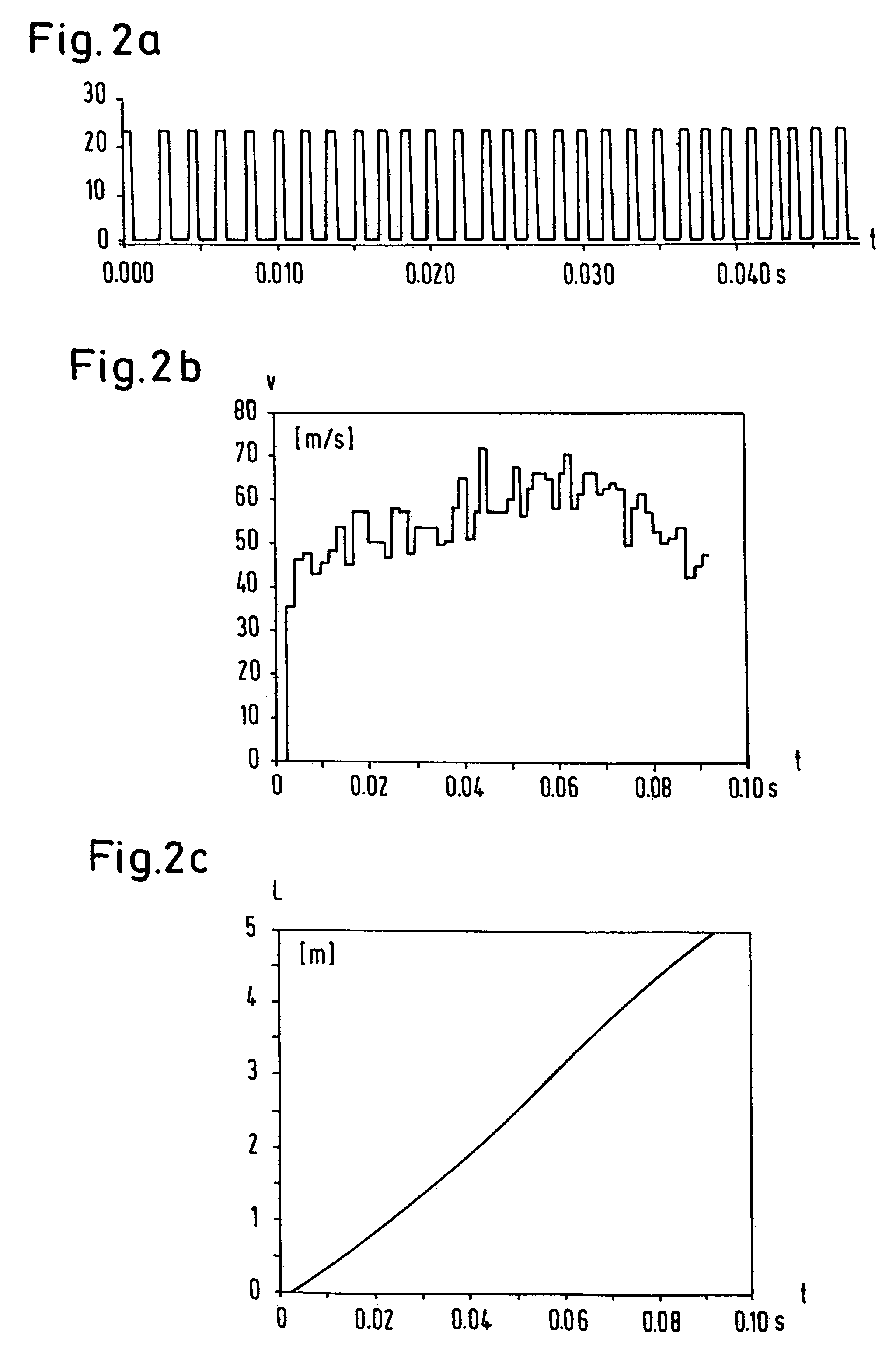
[0021]The system in accordance with the present invention has an advantage in that it is substantially built up of system components which are currently present in most of the standard weaving machines. The only new system component required is an addition to the control program in which certain advantageous functions are implemented. In addition, the system and method in accordance with the present invention enables the compressed air consumption to be reduced substantially with respect to the older machines without having to tolerate losses in cloth quality, since the weft yarn is not loaded by the compressed air any more than is necessary. Forming a predictor value for the position of the weft thread tip, as a result of measurement values which can be determined outside the shed, enables corrections to be made during the momentary weft insertion and in so doing to dispense with sensors and weft thread monitors in the shed. The danger of the cloth quality being impaired by sensors and weft thread monitors which are arranged in the shed is thereby avoided.

Problems solved by technology

The method which is described in EP 0 554 222 A1 is relatively complicated and expensive, since it requires three separate compressed air supplies for the auxiliary nozzles.
Furthermore, the simultaneous charging of a plurality of groups of auxiliary nozzles admittedly permits a careful acceleration of the weft thread, which is however associated with a drastically increased consumption of compressed air.
In addition, the arrangement of a large number of weft thread monitors in the shed is problematical, since the former damage the warp threads and can thereby influence the cloth quality.

Method used


Image

  • System and method for inserting a weft thread
  • System and method for inserting a weft thread
  • System and method for inserting a weft thread

Examples


Embodiment Construction

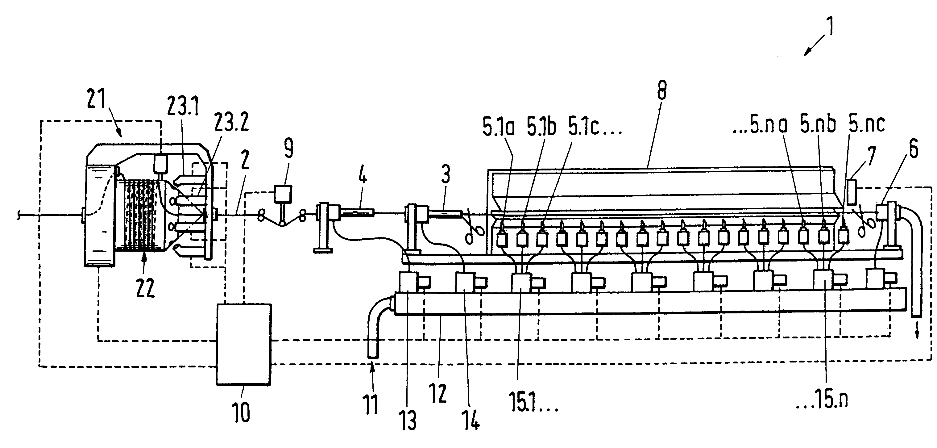
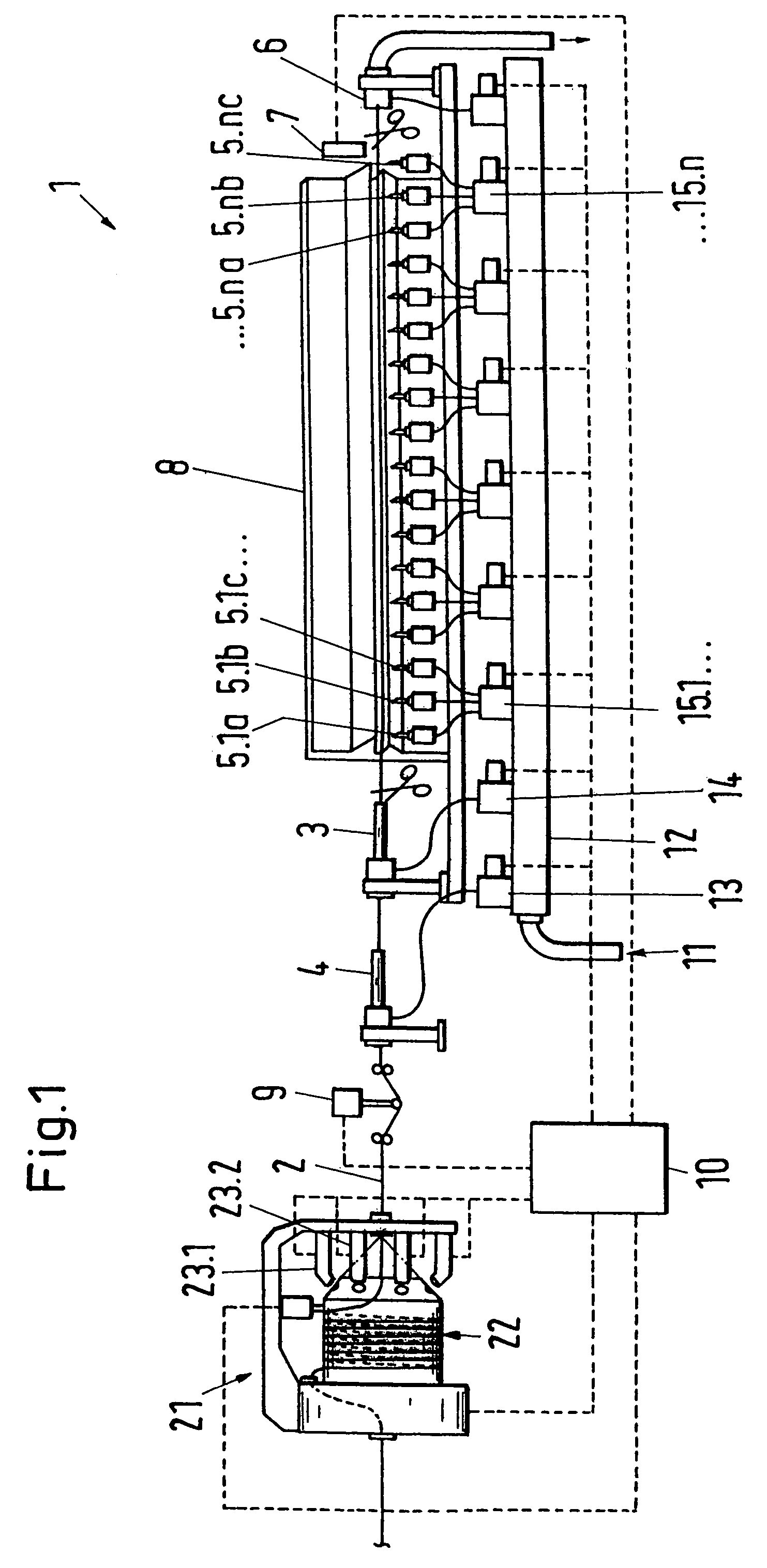
[0031]FIG. 1 shows an exemplary embodiment of an air jet weaving machine 1 including a system in accordance with the present invention. The system for inserting a weft thread 2 into a shed (not illustrated in FIG. 1) includes a thread store 21 and a measuring apparatus 23.1, 23.2 in order to be able to measure the weft thread 2 which is drawn off from the thread store, and in particular in order to be able to measure the length and / or the speed of the drawn-off weft thread, said measuring apparatus preferably being arranged outside the shed, for example at the thread store 21 or in the vicinity of the thread store. Furthermore, the system includes a plurality of air nozzles 3, 4, 5.1a–c to 5.na–c for the insertion of a weft thread 2 and a control system 10 which is connected to the measuring apparatus 23.1, 23.2 in order to be able to control the compressed air supply of the air nozzles 3, 4, 5.1a–c to 5.na–c in dependence on measurement values of the measuring apparatus 23.1, 23.2....


PUM


Abstract

A system for inserting a weft thread into a shed of an air jet weaving machine includes a thread store with a measuring apparatus, a plurality of air nozzles for the insertion of the weft thread and a control system which is connected to the measuring apparatus in order to be able to control the compressed air supply of the air nozzles in dependence on measurement values of the measuring apparatus. Switch-on points are associated with the air nozzles, with the control system charging one or more of the air nozzles with compressed air as soon as a predictor value for the position of the weft thread tip, which is formed with the help of the measurement values, reaches the switch-on point of the relevant air nozzle or air nozzles respectively.

Description

BACKGROUND OF THE INVENTION[0001]The invention relates to a system and a method for inserting a weft thread into a shed of an air jet weaving machine.[0002]In an air jet weaving machine, the weft thread which is drawn off from a thread store is accelerated by main and tandem nozzles and inserted into a shed, in which it is further transported by so-called auxiliary or relay nozzles. In conventional air jet weaving machines the relay nozzles are switched on and off by a pre-selected profile which is firmly connected to the rotation of the main machine shaft. It is left up to the weaving master to ideally adapt this profile for a definite article, with more attention generally being paid to the cloth quality than to the air consumption.[0003]In the specification EP 0 554 222 A1 a method is described for the regulation of the weft insertion for a jet weaving machine with a plurality of weft thread monitors which are arranged in the shed in order to be able to determine the time point a...

Claims


Application Information

Patent Timeline
IPC IPC(8): D03D47/30D03D47/34
CPCD03D47/3033D03D47/34D03D47/304
Inventor SIEGL, WALTERBERKTOLD, KLAUS
Owner SULTEX AG
Learn More