Spindle unit with switchable gear, and method for using the spindle unit

a spindle unit and gear switch technology, applied in the field of spindle units, can solve the problem of not being able to remove the anterior spindle from the drive unit,

Active Publication Date: 2006-06-20
SIEMENS AG
View PDF15 Cites 22 Cited by
  • Summary
  • Abstract
  • Description
  • Claims
  • Application Information

AI Technical Summary

Benefits of technology

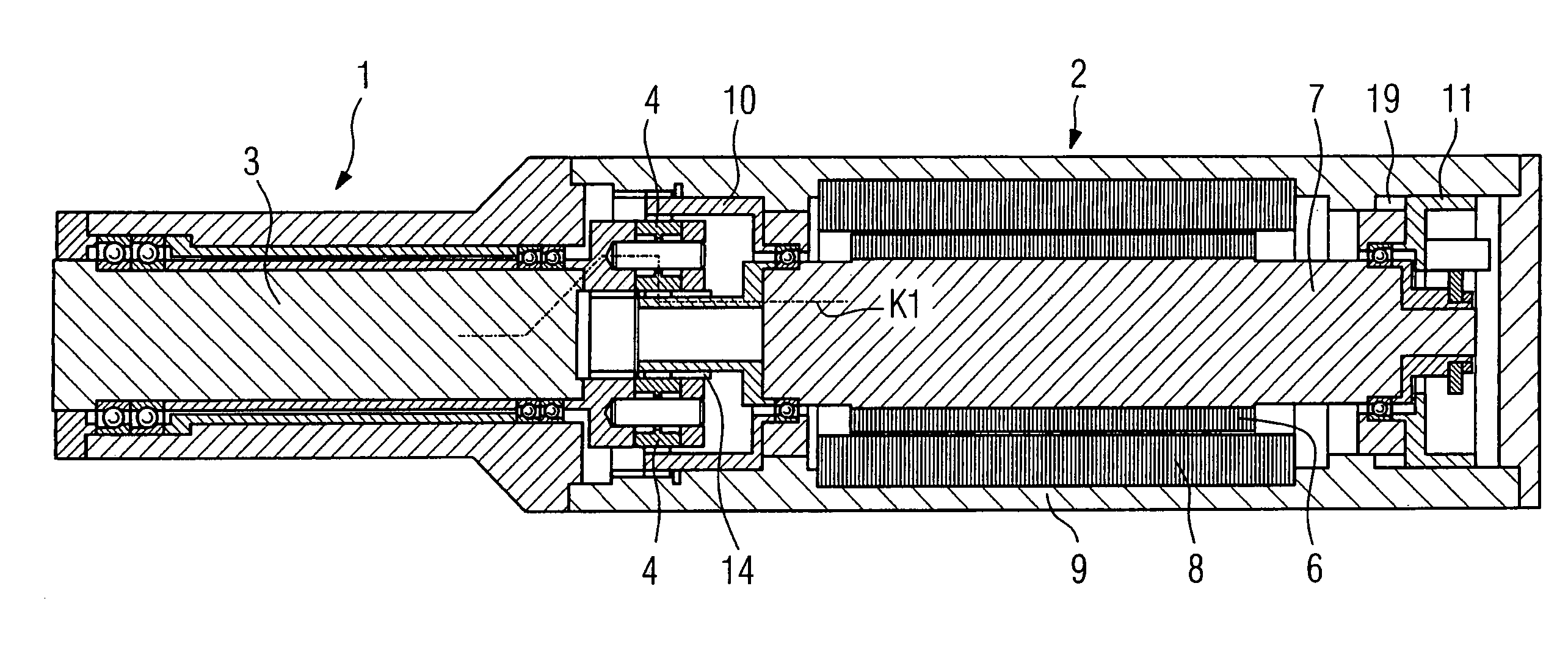
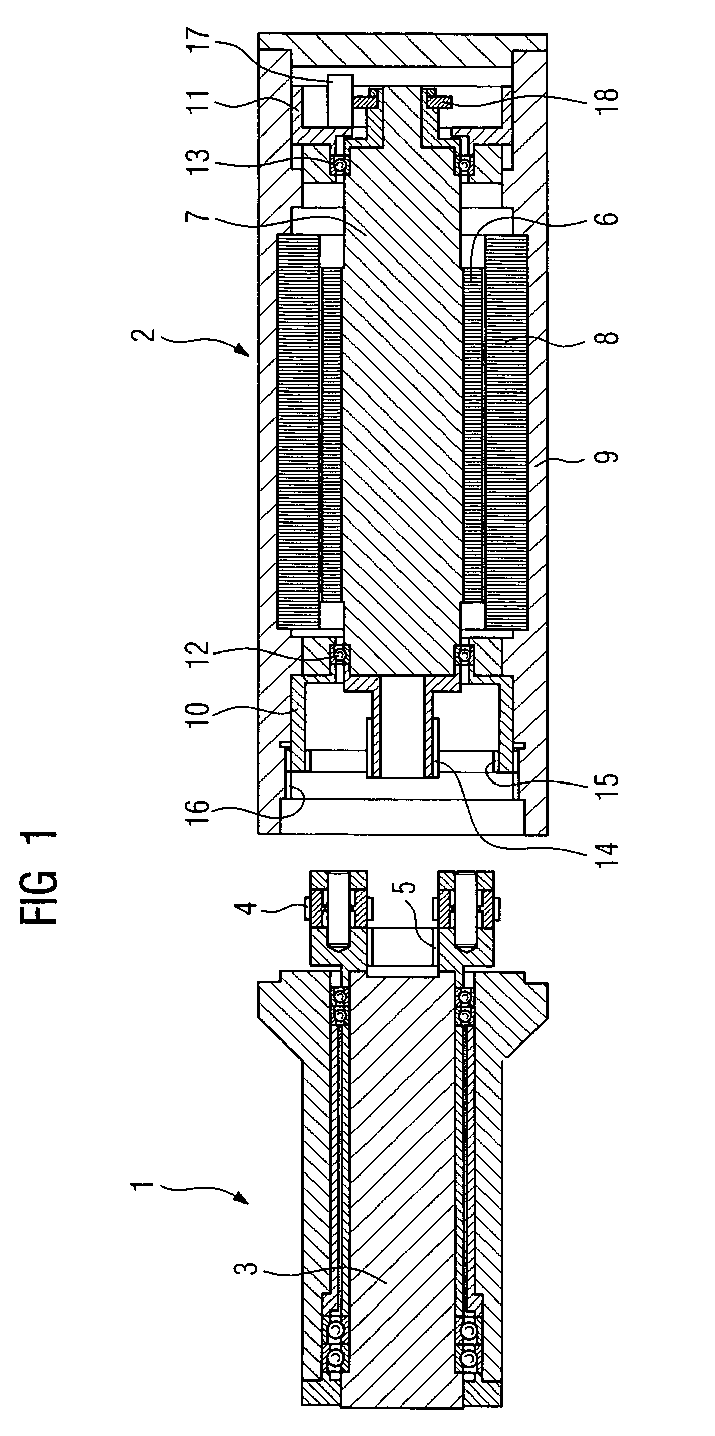
[0012]According to another feature of the present invention, the spindle head assembly can be constructed for removal from the drive unit. This allows different spindle heads and/or anterior spindles to be used with different tool chucks.
[0013]According to another feature of the present invention, the spindle unit can also include an axially displaceable bearing assembly that supports the drive shaft. In particular, the bearing assembly

Problems solved by technology

However, it would be undesirable to require removal of the anterior spindle f

Method used


Image

  • Spindle unit with switchable gear, and method for using the spindle unit
  • Spindle unit with switchable gear, and method for using the spindle unit
  • Spindle unit with switchable gear, and method for using the spindle unit

Examples


Embodiment Construction

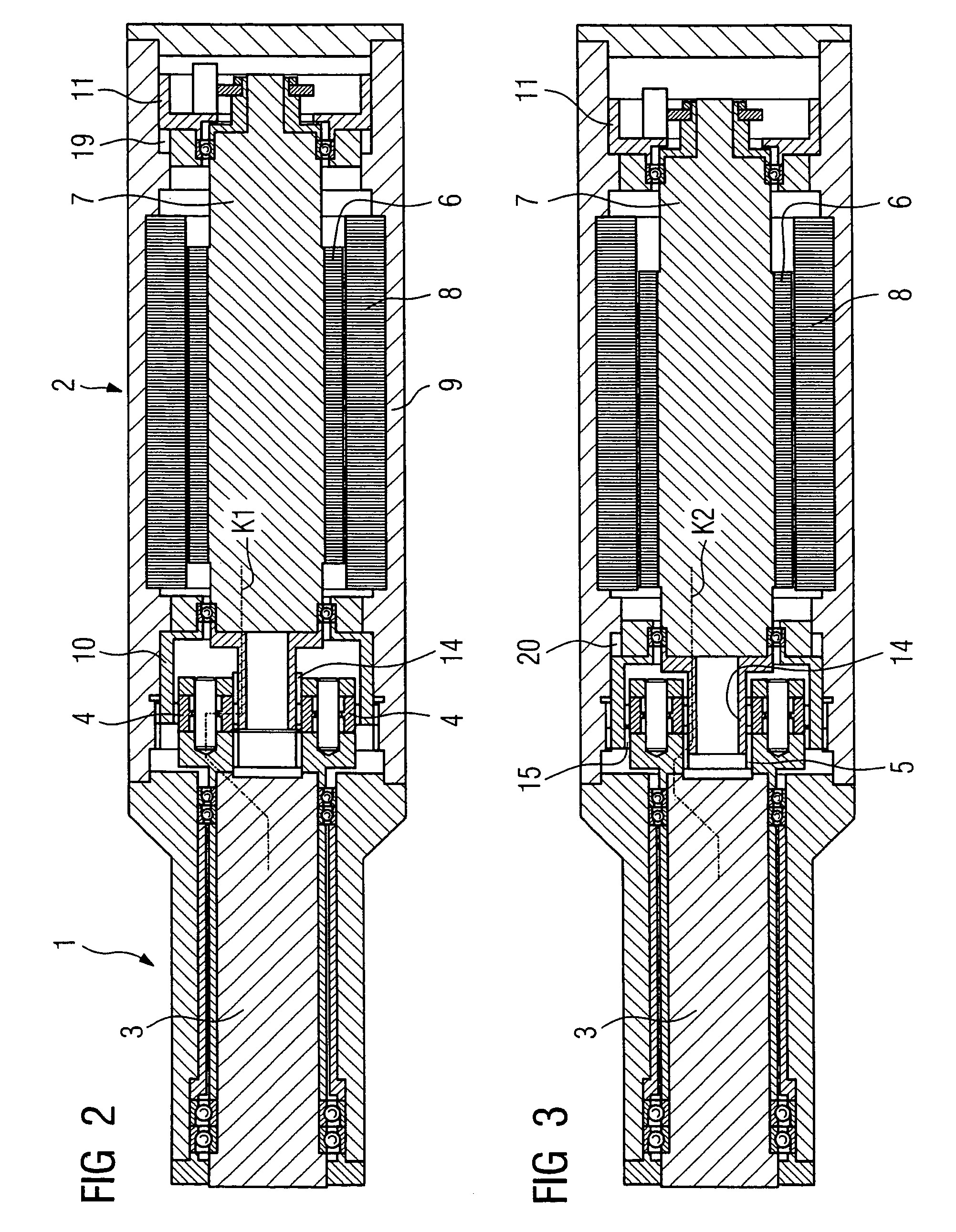
[0020]Throughout all the Figures, same or corresponding elements are generally indicated by same reference numerals. These depicted embodiments are to be understood as illustrative of the invention and not as limiting in any way. It should also be understood that the drawings are not necessarily to scale and that the embodiments are sometimes illustrated by graphic symbols, phantom lines, diagrammatic representations and fragmentary views. In certain instances, details which are not necessary for an understanding of the present invention or which render other details difficult to perceive may have been omitted.

[0021]This is one of two applications both filed on the same day. Both applications deal with related inventions. They are commonly owned and have the same inventive entity. Both applications are unique, but incorporate the other by reference. Accordingly, the following U.S. patent application is hereby expressly incorporated by reference: “SPINDLE FOR A MACHINE TOOL WITH IMPR...


PUM


Abstract

A system and a method are described that facilitate gear switching of a motor-driven spindle. A spindle head shaft is driven by a drive shaft via a gear mechanism in a first gear position. The drive shaft, including a rotor, can be switched from the first gear position to a second gear position where the spindle head shaft is connected by interference fit directly with the drive shaft without the interposed gear mechanism. The spindle head shaft can then be directly driven by the drive shaft in the second gear position. This eliminates the need to dismantle an anterior spindle from the drive unit.

Description

CROSS-REFERENCES TO RELATED APPLICATIONS[0001]This application claims the priority of German Patent Application, Serial No. 103 16 245.3, filed Apr. 9, 2003, pursuant to 35 U.S.C. 119(a)–(d), the disclosure of which is incorporated herein by reference.BACKGROUND OF THE INVENTION[0002]The present invention relates to a spindle unit for machine tools that facilitates switching of the rotation speed of the spindle unit. The present invention also relates to a method for operating a spindle unit of this type.[0003]Spindle units are employed, for example, in motor-driven milling machines. A motor-driven milling spindle can be made as a single-piece or of separable components and typically includes an electric motor with a shrink-fit rotor. The rotor is supported between two bearings blocks. A tool tensioning system that typically includes a chucking head, a tie rod and a disk spring arrangement is arranged in the interior of the shaft. A tensioning system sensor located on the tie rod an...

Claims


Application Information

Patent Timeline
IPC IPC(8): B23B19/02B23Q5/04F16H3/54
CPCB23Q5/048F16H2200/0034F16H3/54
Inventor HERLA, MAX
Owner SIEMENS AG
Why Eureka
Try Eureka