
Cervical stabilization device

a cervical stabilization and cervix technology, applied in the field of cervical stabilization devices, can solve the problems of weakened cervix, crippling lifelong diseases of infants surviving preterm birth, and affecting the ability of the cervix to handle the added pressure, and make future pregnancies even more difficul

Active Publication Date: 2013-10-08
VIATECHMD
View PDF20 Cites 15 Cited by
  • Summary
  • Abstract
  • Description
  • Claims
  • Application Information

AI Technical Summary

Benefits of technology

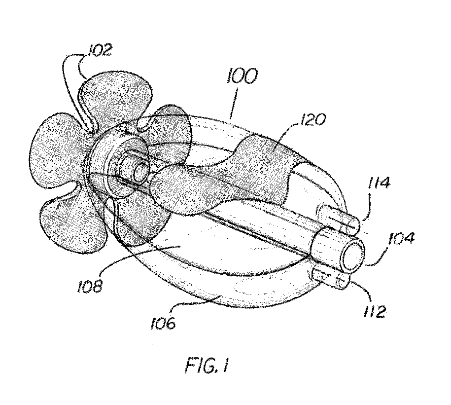
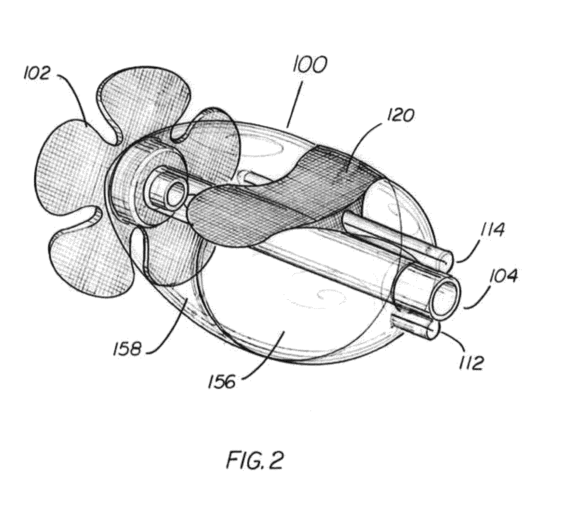
[0010]Particular implementations of a device for stabilizing a uterus may comprise one or more of the following: The external retaining portion may further comprise a vent coupled to the vent of the support, the external retaining portion vent in communication with the vent of the nesting area and outside the vagina. The external retaining portion may be configured to couple to the woman outside the vagina through at least one of a belt and a garment positioned around the woman.
[0011]In yet another aspect, a method of stabilizing a cervix during pregnancy may comprise at least partially surrounding a cervix of a uterus carrying a fetus with a nesting area of a cervical stabilization device without engaging the cervix, permitting the cervix to drain fluid from the nesting area through a vent in the nesting area, supporting a portion of a vaginal wall of a vagina proximate entry of the cervix of the uterus into the vagina with a uterine support shoulder of the cervical stabilization device, the uterine support shoulder at least partially surrounding the nesting area, and maintaining the support of the portion of the vaginal wall proximate entry of the cervix into the vagina through engaging vaginal walls surrounding the cervix with at least one seat portion coupled to and extending anatomically outward and downward from the uterine support shoulder.
[0012]Particular implementations of a method of stabilizing a cervix during pregnancy may further comprise one or more of the following: Inserting the cervical stabilization device into the vagina prior to supporting a portion of the vaginal wall proximate the entry of the cervix of the uterus into the vagina and permitting the cervix to further drain the fluid through a vent tube coupled to the vent in the nesting area. Maintaining the support of the portion of the vaginal wall proximate entry of the cervix through engaging vaginal walls surrounding the cervix may comprise engaging the vaginal walls for an extended period of time without removing the cervical stabilization device. Maintaining the support of the portion of the vaginal wall proximate the entry of the cervix of the uterus into the vagina for an extended period of time may comprise maintaining the support at least a week and the maintaining the support at least a week may comprise maintaining the support for at least a month without removing the cervical stabilization device. Particular implementations may further comprise inflating at least one bladder portion positioned beneath the at least one seat portion such that when the at least one bladder is inflated it enlarges and pushes the at least one seat portion toward the vaginal walls surrounding the cervix. Particular implementations may further comprise inflating the at least one bladder portion such that an anatomically lower portion of the at least one bladder portion contacts anatomically lower vaginal tissues proximate an anatomically lower pelvic structure adjacent the vagina. The method may further comprise inflating at least a second bladder adjacent to the at least one bladder, the at least a second bladder positioned beneath the at least one seat portion on a second side of the nesting area. The method may further comprise inflating at least a second bladder adjacent to the at least one bladder, the at least a second bladder being positioned along a vent tube coupled to the vent in the nesting area.

Problems solved by technology

Moreover, infants surviving preterm birth often suffer crippling lifelong diseases including autism and cerebral palsy (conditions known to result from premature birth).
A patient with an incontinent cervix has a weakened cervix that may not be able to handle the added pressure on the cervix resulting from pregnancy.
Moreover, cerclage is known to further compromise the cervix which can make future pregnancies even more difficult, and the procedure is also often associated with an instantaneous premature birth event.

Method used


Image

  • Cervical stabilization device
  • Cervical stabilization device
  • Cervical stabilization device

Examples


Embodiment Construction

[0023]The following descriptions are of exemplary embodiments of particular implementations of cervical stabilization devices and are not intended to limit the scope, applicability or configuration of the claims in any way. Rather, the following descriptions are intended to provide convenient illustrations for implementing various embodiments of cervical stabilization devices. As will become apparent, changes may be made in the function and / or arrangement of any of the elements described in the disclosed exemplary embodiments without departing from the spirit and scope of the claims.

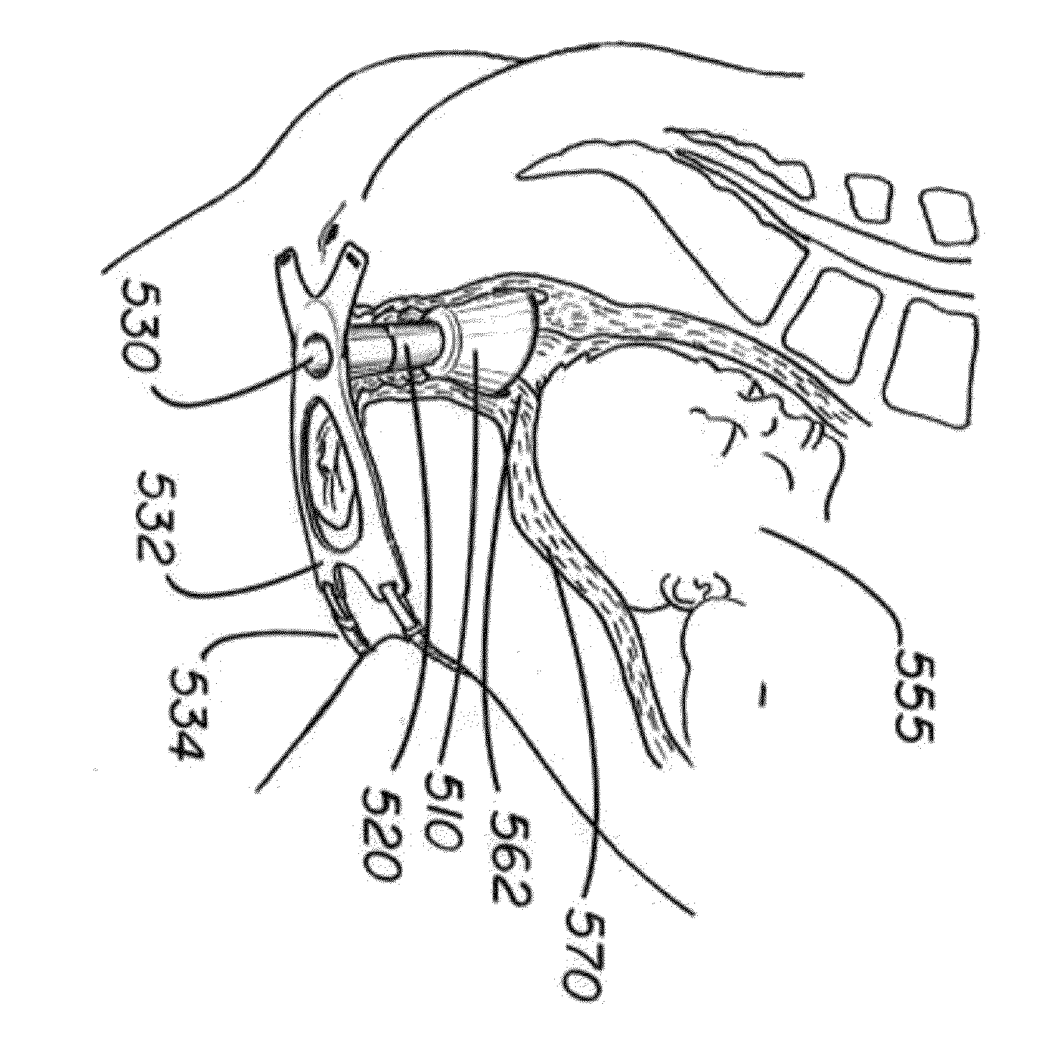
[0024]Embodiments provide for a device that is used to stabilize the cervix, relieving some of the weight bearing down upon the uterus so as to reduce unnecessary strain on or stimulation of the cervix. Conventional devices, used as contraceptives or to retain prolapsed organs (such as the balder, bowel, and uterus) and which are not used or intended for use during pregnancy or to prevent premature birth...


PUM


Abstract

A system and method for stabilizing an incontinent cervix during pregnancy are described. A system may include a nesting portion designed to surround the cervix without applying pressure to the cervix, while supporting the uterus in opposition to the weight of the developing fetus to prevent untimely effacement and dilatation of the cervix; thereby reducing the risk of premature birth and its consequence.

Description

CROSS REFERENCE TO RELATED APPLICATIONS[0001]This application claims priority to the following U.S. Provisional Patent Applications: 61 / 089,428, filed Aug. 15, 2008, and 61 / 164,815, filed Mar. 30, 2009, the disclosures of each of which are hereby incorporated by reference in their entirety.BACKGROUND[0002]1. Technical Field[0003]This disclosure relates to implementations of a device, with at least some portion thereof designed to be inserted into the vagina, for the purpose of stabilizing the cervix and uterus during pregnancy. Particular implementations may reduce the risk of miscarriage, premature delivery, or stillbirth, resulting from compromise of the organs and structures of the female reproductive system.[0004]2. Background Art[0005]A medical condition commonly known as an “incontinent cervix” (also known as an “insufficient cervix”, “incompetent cervix” and “loose cervix”) can have serious effects on a pregnant woman and is known to be responsible for the loss of millions of...

Claims


Application Information

Patent Timeline
Patent Type & Authority Patents(United States)
IPC IPC(8): A61F13/00
CPCA61B17/4241A61F6/08A61B2017/00557A61B2017/00902A61B2017/4225
Inventor BOOHER, SR., BENJAMIN V.
Owner VIATECHMD
Learn More