Ink jet printer

Inactive Publication Date: 2006-06-20
BROTHER KOGYO KK
View PDF20 Cites 18 Cited by
  • Summary
  • Abstract
  • Description
  • Claims
  • Application Information

AI Technical Summary

Benefits of technology

[0017]The tubes supplying the ink therethrough from the ink container provided separately from the print head may be protruded from the surface of the print head on both end sides in the moving direction of the print head, and may be set with the flat cables that supply the current to the print head. Thus, widths of the tube member and the flat cable may be reduced to half, so that demands for a mobile printer, such as compactness and thinness m

Problems solved by technology

When the tube contacts the roller, the tube is caught on a frictional member (such as rubber and coating) provided on a surface of the roller, so that a resistance may be applied to the print head during its movement or the tube may be damaged by the roller rubbing the surface of the tube.
Accordingly, the resistance to the movement of the print head causes a change in a moving speed of the print head, so that positions

Method used


Image

  • Ink jet printer
  • Ink jet printer
  • Ink jet printer

Examples


Embodiment Construction

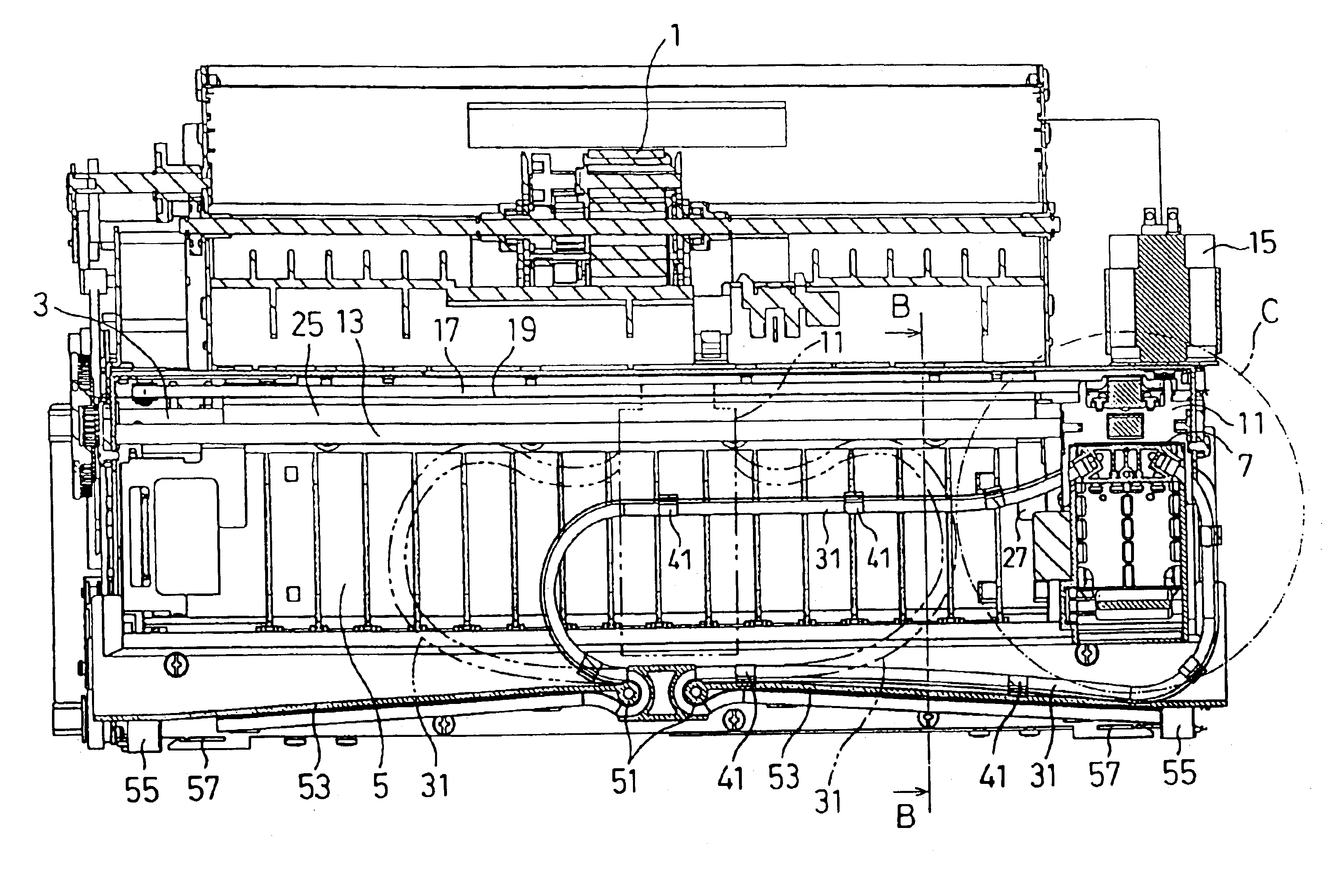
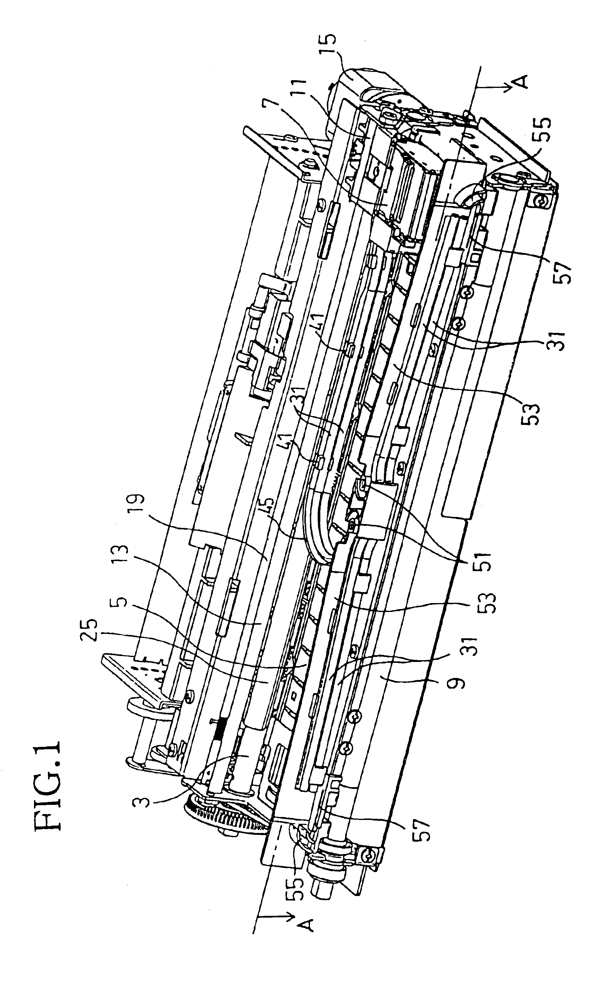
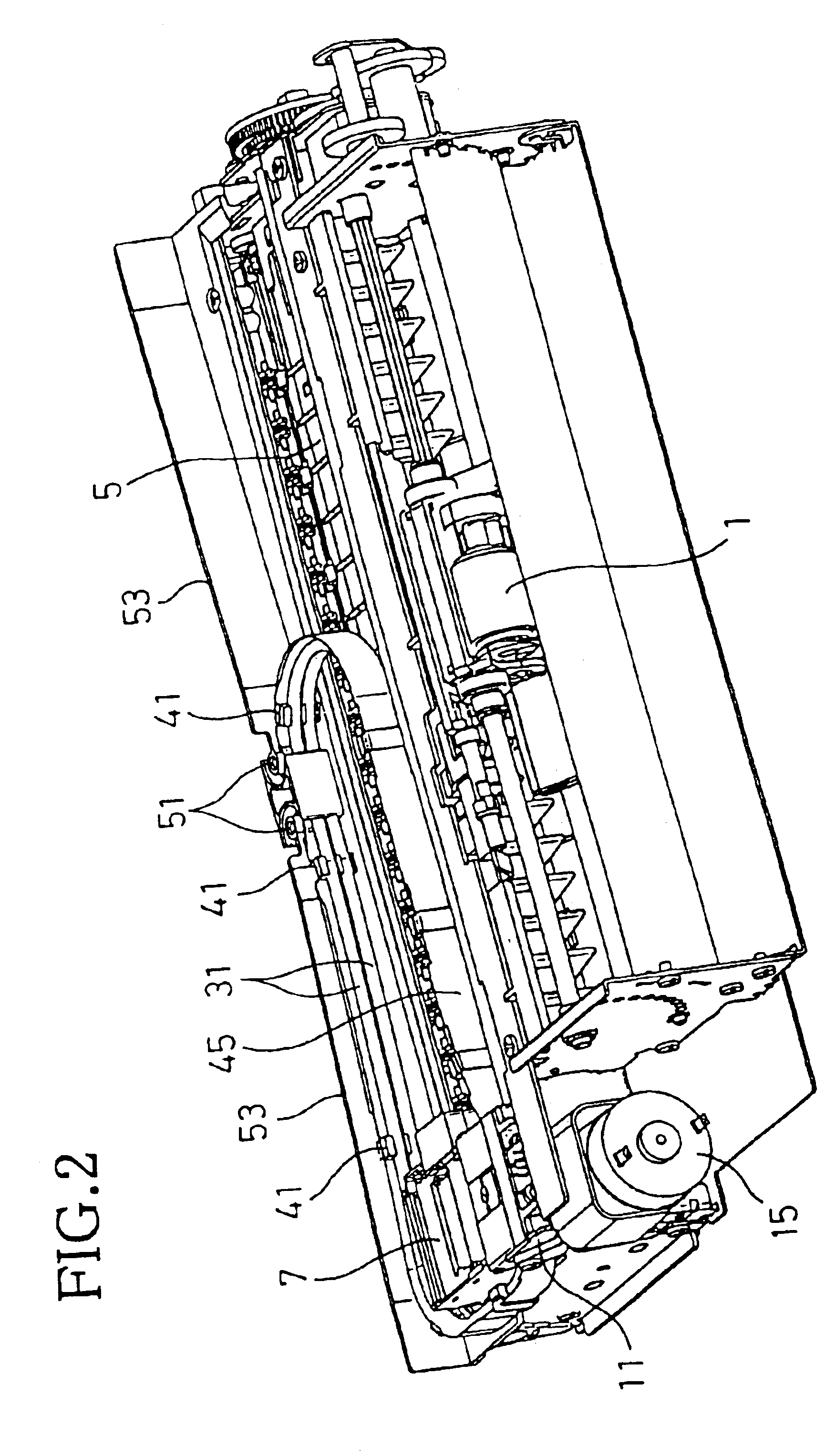
[0031]An ink jet printer according to an embodiment of the invention will be described with reference to the accompanying drawings. FIG. 1 is a perspective view showing an internal structure of the ink jet printer from a sheet discharging side, that is, from a downstream side in a sheet feeding direction (hereinafter referred to as the front side). FIG. 2 is a perspective view showing the internal structure of the ink jet printer from a sheet feeding side, that is, from an upstream side in the sheet feeding direction (hereinafter referred to as the rear side). As shown in FIG. 2, the ink jet printer is provided with a feed roller 1 at a rear portion thereof The feed roller 1 separates recording sheets (recording media) stacked on a sheet feed tray (not shown), one by one, and feeds the separated recording sheet in the sheet feeding direction. The recording sheet fed by the feed roller 1 is conveyed to a platen 5 by a transport roller 3 shown in FIG. 1. An image is formed with a prin...


PUM


Abstract

An ink jet printer includes an ink container supplying ink through a tube member to a separate print head to form an image. The ink jet printer also includes a guide rail to guide the print head, a transport roller to feed the recording medium, and a cover to prevent the tube member from contacting the roller. As the print head reciprocates in a width direction of a recording medium, the tube protruding from a surface of the print head on an end side in a moving direction thereof bends or flexes when the print head moves together with a carriage. The bending of the tube in the rearward direction is restricted by a tube band contacting the transport roller and cover. The cover and guide rail form a plane vertical to a platen at front faces of the cover and the guide. When the bending or movement of the tube is blocked or restricted by the vertical plane to a tube bending direction, the tube is not raised. Therefore, a resistance is not applied to the print head during the movement of the print head. Thus, the bending or movement of the tube can be restricted without providing a special device for the ink jet printer.

Description

[0001]This is a Continuation of application Ser. No. 10 / 315,167 filed Dec. 10, 2002 now U.S. Pat. No. 6,755,514. The entire disclosure of the prior application is hereby incorporated by reference herein in its entirety.BACKGROUND OF THE INVENTION[0002]1. Field of Invention[0003]The invention relates to an ink jet printer that ejects ink from a print head to form an image on a recording medium, and, more particularly, to a serial-type ink jet printer that forms the image by supplying the ink through a tube to the print head reciprocating in a width direction of the recording medium.[0004]2. Description of Related Art[0005]Some conventional ink jet printers are separately provided with an ink container that contains ink and a print head. The ink is supplied to the print head from the ink container through a tube. Such structure enables the print head to be reduced in size, as compared to a structure where the print head is integrally provided with the ink container. If a serial-type i...

Claims


Application Information

Patent Timeline
IPC IPC(8): B41J2/175
CPCB41J2/175B41J2/17523B41J2/17509B41J2/17503B41J19/005
Inventor KOGA, YUJI
Owner BROTHER KOGYO KK
Why Eureka
Try Eureka